
Pressure reduction phase
- Make
- Fiat
- Model
- Bravo /Brava (182) Factory Service Manual
- Year
- 1995–2001
- Section
- Anti-lock braking system › Pressure reduction phase
Pressure reduction phase
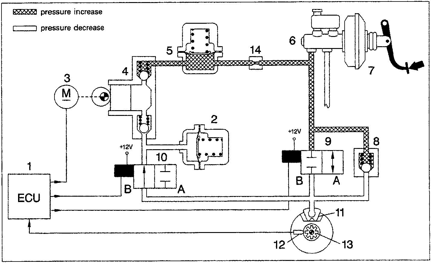
- Electronic control unit
- Low-pressure accumulator (reservoir)
- Recycling pump motor
- Recycling pump
- High-pressure accumulator (damping chamber)
- Brake pump
- Servo unit
- Rapid pressure reducing valve
- Inlet solenoid (A) open (B) closed
- Outlet solenoid (A) closed (B) open
- Brake caliper
- Rpm sensor
- Phonic wheel
- Constriction
The electronic control unit (1) detects the wheel's tendency to lock and activates the electrohydraulic unit to limit the wheel deceleration to within the permitted threshold values.
The electronic control unit (1) earths the inlet solenoid (9) and outlet solenoid (10).
The inlet solenoid (9) remains closed, maintaining the break in connection between brake pump (6) and brake caliper (11); the outlet solenoid (10) opens thus hydraulically connecting the brake caliper (11) to the low-pressure accumulator (2) and recycling pump (4), in order to remove some of the fluid from the brake caliper (11) and reduce the pressure on that caliper.
At the same time the electronic control unit (1) supplies the motor (3) for driving the recycling pump (4) which returns fluid removed from the brake caliper (11) into the main circuit. The accumulator (2) or low pressure reservoir present in the circuit stores some of the brake fluid removed from the calipers. Through the circuit of the recycling pump (4), the brake fluid is drawn in and sent, through the damping chamber (5) and constriction (14), into the main circuit of the brake pump (6). During this phase, a series of pressure waves (or hydraulic thrusts) is generated, and these are attenuated by the presence of the damping chamber (5) and constriction (14). During this phase, because of the reduction in the braking force, the wheel tends to assume the reference speed calculated by the electronic control unit (1).
Parts & tools for this job For 1995 Fiat Bravo
- TOOLTorque wrenchSearch: 3/8 inch torque wrench
- TOOLSocket setSearch: socket set metric
- BOOKHaynes manualSearch: Haynes manual Fiat Bravo
Links open Amazon search results in a new tab. As an Amazon Associate I earn from qualifying purchases.