
Controls mounting assembly
- Make
- Fiat
- Model
- Bravo /Brava (182) Factory Service Manual
- Year
- 1995–2001
- Section
- Manual heater › Controls mounting assembly
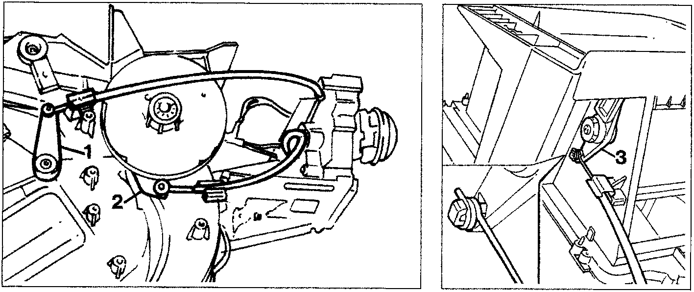
After fitting onto the pins of the levers (1, 2 and 3) the coiled eyelet ends of the flexible transmission cables, the cable sheaths must be secured to the heater-distributor unit by their clips so that the various flaps execute their full travel.
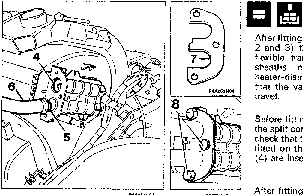
Before fitting the two metal pipes (6) in the split connector of the heater radiator, check that the tapered metal rings (5) are fitted on the ends, and that the O-rings (4) are inserted in the seating holes.
After fitting the above-mentioned pipes in the split connector of the heater radiator, secure the latter by means of the plate (orientated as shown in the figure) and bolts (8), taking care not to damage the seals.
CONTROLS MOUNTING ASSEMBLY
Removing
- remove the dashboard;
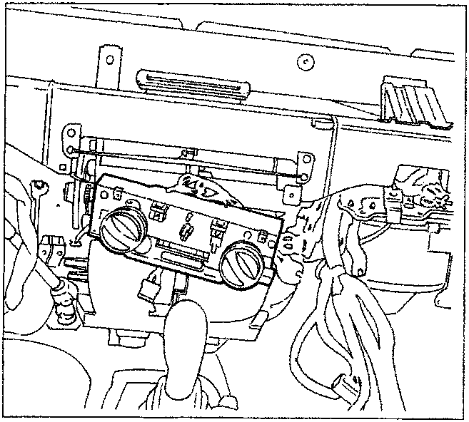
Detail of the controls mounting assembly with the dashboard removed
Parts & tools for this job For 1995 Fiat Bravo
- TOOLA/C manifold gauge setSearch: AC manifold gauge set
- TOOLUV leak detection kitSearch: AC UV leak detection kit
- PARTCabin filterSearch: Fiat Bravo 1995 cabin filter
Links open Amazon search results in a new tab. As an Amazon Associate I earn from qualifying purchases.