
5. (page 2 of 2)
- Make
- Fiat
- Model
- Bravo /Brava (182) Factory Service Manual
- Year
- 1995–2001
- Section
- Air bag
55 Electrical system5. · page 2 of 2
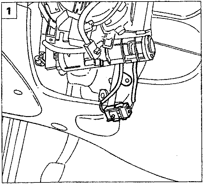
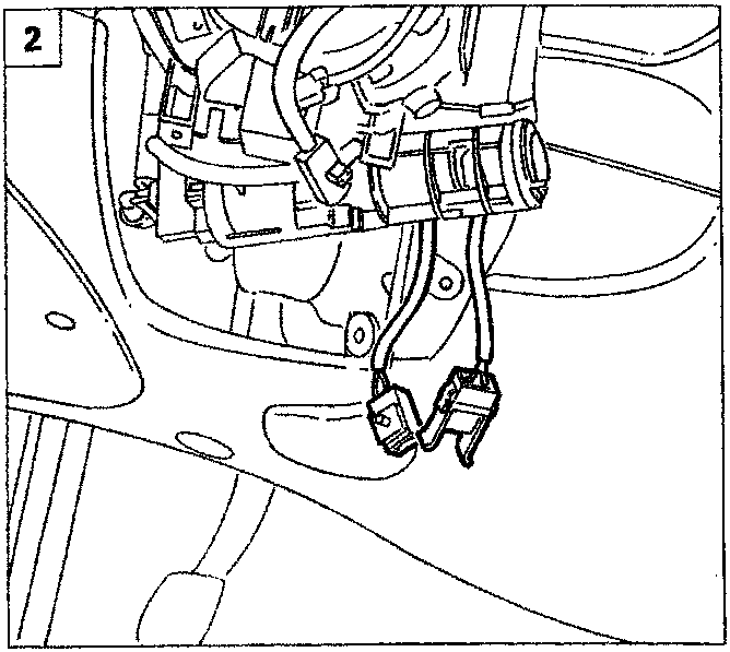
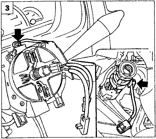
- Disconnect the yellow connector from the ignition switch bracket.
- Disconnect the yellow connector connecting the air bag control unit to the clock spring.
- Release the clock spring lead from its retaining leads.
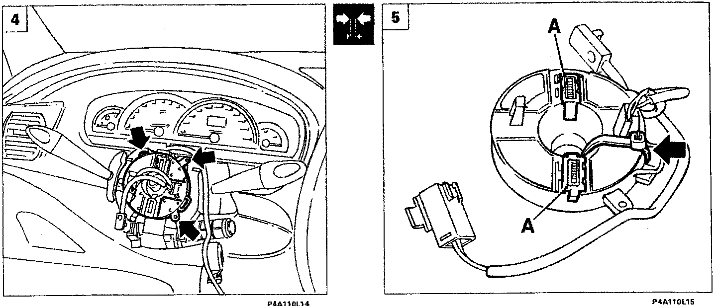
- Undo the three cross-headed screws retaining the clock spring and remove from the vehicle.
The clock spring is fitted with a system to prevent rotation (clip A fig. 5). This operates when the steering wheel is removed.
- For greater safety, prevent the clock spring from turning by using a clip or adhesive tape as indicated by the arrow.

Parts & tools for this job For 1995 Fiat Bravo
- TOOLOBD2 scanner with SRSSearch: OBD2 scanner ABS SRS
- TOOLTrim removal tool kitSearch: trim removal tool kit
Links open Amazon search results in a new tab. As an Amazon Associate I earn from qualifying purchases.