
Steering electrical control device - r r
- Make
- Fiat
- Model
- Idea Factory Service Manual
- Year
- 2003–2012
- Section
- Steering control and linkage › Steering electrical control device - r r
Steering electrical control device - r r
Removing
Make sure that the ignition key is in the OFF position. then disconnect the battery negative (-) terminal.
| Name | Connector | |
|---|---|---|
| Battery | A1B |
Wait for at least 20 seconds after the engine has been switched off before disconnecting the battery to allow the electro-control steering device to finish its switching off procedure.
Proceed with removal - 7040L37 gear lever plate - r r
Proceed with removal - 7040A65 passenger compartment box lock, one, r r
Proceed with removal - 7040A19 cushion padding - r r
Proceed with removal - 7040A28 TRIM on gearbox control panel - R.R.
Proceed with removal - 7040A30 Left instrument panel lower TRIM - R.R.
Proceed with removal - 5580C18 air bag module - r+r
Closely observe the safety regulations established for this operation. See assembly 5580C air bag system
Check that the steering is perfectly locked to prevent accidental rotation.
Proceed with removal - 4110A11 steering wheel - r+r for replacement or check for versions with air bag
Proceed with removal - 5550A12 complete stalk unit - r+r for versions with air bag
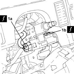
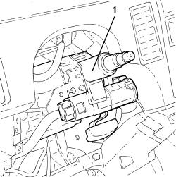
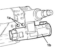
1. Disconnect the electrical connections from the ignition lock (1a) and from the anti-theft aerial (1b).
| Name | Connector | |
|---|---|---|
| 1a | Ignition switch | H1 |
| Name | Connector | |
|---|---|---|
| 1b | Aerial for central locking receiver | P93 |
Release the ignition key detection ring from the ignition switch.
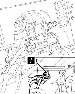
1. Disconnect the electrical connections from the electric steering control unit.
| Name | Connector | |
|---|---|---|
| 1 | Electric steering control unit | M86 |
2. Undo the bolt fixing the steering control shaft to the steering box pinion.
The outer casing of the electric steering device may reach high temperatures following repeated manoeuvres at full load (parking or repeated operations at low speed); it is advisable to check whether the device is hot before touching it.
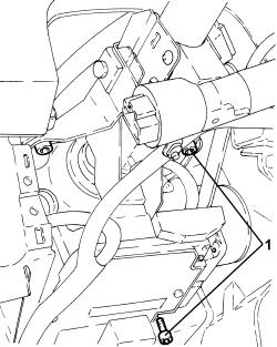
1. Undo the bolts securing the electric steering device to the dashboard crosspiece.
The electric steering device weighs about 11 kg. It is therefore recommended to remove it carefully.
1. Lower the electric steering device and rotate it in a clockwise direction, then extract it and remove it.
Follow the instructions for moving the electric steering device See assembly 4110D steering electrical control system
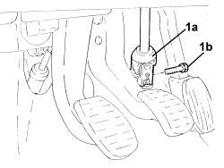
1. When replacing the electric steering device, at the bench, undo the bolts (1a) and remove the ignition switch (1b).
Refitting
When fitting a new electric steering device, reposition the ignition switch in its housing and secure it using the bolts.
Move the steering column shaft to the minimum length and position the bottom fork on the connection with the steering box pinion.
Fit the electric steering device in its housing, rotating it to the right in relation to the assembly position.
Follow the instructions for moving the electric steering device See assembly 4110D steering electrical control system
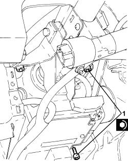
1. Tighten the bolts fixing the electric steering device to the dashboard crossmember to the recommended torque.
| Fastening | Component | Ø | Value (daNm) | |
|---|---|---|---|---|
| 1 | Bolt | STEERING ELECTRIC CONTROL DEVICE | M8 | (Dashboard crossmember side) 2.0 ÷ 2.4 |
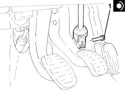
1. Tighten the bolt fixing the steering control shaft for the steering box to the recommended torque.
Use a new bolt to fasten the steering control shaft to the steering box pinion.
| Fastening | Component | Ø | Value (daNm) | |
|---|---|---|---|---|
| 1 | Bolt | INTERMEDIATE SHAFT CONNECTED TO STEERING BOX. | M10 | (Steering box side) 5.0 ÷ 6.1 |
If a new electric steering device has been fitted, remove the anti-rotation stop which accompanies the new unit.
Connect the electrical connections to the electric steering device control unit.
Connect the electrical connections for the ignition switch block and the anti-theft aerial.
Proceed with removal - 5550A12 complete stalk unit - r+r for versions with air bag
Proceed with removal - 4110A11 steering wheel - r+r for replacement or check for versions with air bag
Proceed with removal - 5580C18 air bag module - r+r
Proceed with removal - 7040A30 Left instrument panel lower TRIM - R.R.
Proceed with removal - 7040A28 TRIM on gearbox control panel - R.R.
Proceed with removal - 7040A19 cushion padding - r r
Proceed with removal - 7040A65 passenger compartment box lock, one, r r
Proceed with removal - 7040L37 gear lever plate - r r
Connect the negative (-) battery terminal.
Calibrate the steering angle sensor built into the electronically controlled steering by following the procedure indicated by the Examiner test station.
Parts & tools for this job For 2003 Fiat Idea
- TOOLTie rod end toolSearch: tie rod end puller
- TOOLBall joint separatorSearch: ball joint separator
- FLUIDPower steering fluidSearch: Fiat power steering fluid
Links open Amazon search results in a new tab. As an Amazon Associate I earn from qualifying purchases.