
Components
- Make
- Fiat
- Model
- Seicento Factory Service Manual
- Year
- 1998–2010
- Section
- Description and operation: Electric power steering › Components
In the event of faults, the system allows steering without the power assisted system.
Power assisted steering is not available when the engine is not running to prevent deploying the battery.
COMPONENTS
STEERING COLUMN AND ELECTRICAL MOTOR
The motor and the worm screw are fitted perpendicularly to the steering column. The helicoid wheel is attached to the output shaft. A torsion bar connects the input and output steering shaft.
An angular deflection between the input shaft and the output shaft is created by steering. This is converted into an axial movement of the ring sensor by means of a ball and groove. The movement of the ball in the circular groove is recorded by a potentiometer fitted on the mechanism capsule.
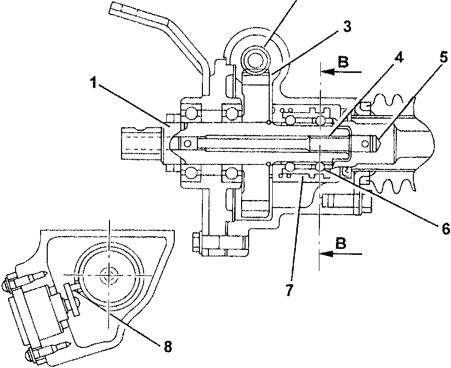
| Ref. | Description |
|---|---|
| 1 | OUTPUT STEERING SHAFT |
| 2 | WORM SCREW |
| 3 | HELICOID WHEEL |
| 4 | TORSION BAR |
| 5 | INPUT STEERING SHAFT |
| 6 | BALL |
| 7 | RING SENSOR |
| 8 | POTENTIOMETER |
The axial movement of the ring sensor is transferred to the potentiometer. Consequently, the steering torque is translated into a proportional electrical output.
Parts & tools for this job For 1998 Fiat Seicento
- TOOLTie rod end toolSearch: tie rod end puller
- TOOLBall joint separatorSearch: ball joint separator
- FLUIDPower steering fluidSearch: Fiat power steering fluid
Links open Amazon search results in a new tab. As an Amazon Associate I earn from qualifying purchases.