
Single cylinder head, removed - overhaul
- Make
- Fiat
- Model
- Ulysse Factory Service Manual
- Year
- 2002–2010
- Section
- Cylinder head/s › Single cylinder head, removed - overhaul
SINGLE CYLINDER HEAD, REMOVED - OVERHAUL
Operation not available.
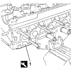
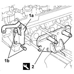
1. Fit the support tool and secure it using the service bolts, then position the cylinder head in the vice.
| Description | Code | Function | |
|---|---|---|---|
| Support | 1.860.170.000 | Cylinder head support |
2. Undo the fixing bolts (2a) and remove the bracket (2b).
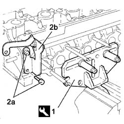
2. Undo the fixing bolts (2a) and remove the bracket (2b).
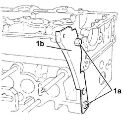
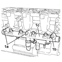
1. Undo the fixing bolts (1a) and the nut (1b) and remove the fuel distribution manifold (common rail) (1c) from the cylinder head.
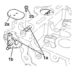
1. Undo the fixing bolts (1a) and rotate the shaft and remove the throttle (1b). Repeat the operation for all the intake manifolds.
2. Release the throttle shaft complete with control lever (2b).
- If necessary, undo the fixing nut and separate the control lever from the throttle shaft.
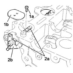
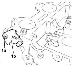
1. Undo the fixing bolt (1a) and remove the bracket for the throttle shaft control lever (1b).
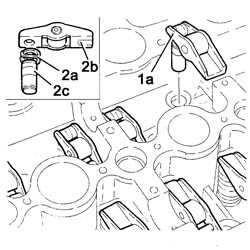
1. Remove the rocker-tappet assemblies (1a).
Mark the position of each unit to facilitate the refitting operations.
2. If necessary, adjust the clips (2a) and separate the rockers (2b) from the hydraulic tappets (2c).
1. Fit the valve retaining tool.
| Description | Code | Function | |
|---|---|---|---|
| Valve retaining base | 1.860.804.000 | Valve spring compression |
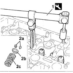
1. Using the tool complete with hook, as illustrated in the diagram, compress the valve springs.
2. Release the caps (2a), cotters (2b) and springs (2c), then remove from the head.
| Description | Code | Function | |
|---|---|---|---|
| Lever | 1.860.644.000 | Spring compression |
1. Remove the valve spring lower seals-cotters (1a) from the valve stems.
- Remove the valve retaining tool fitted previously.
| Description | Code | Function | |
|---|---|---|---|
| Valve retaining base | 1.860.804.000 | Valve spring compression |
Mark the position of the valves and the various components to facilitate the refitting operations.
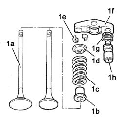
- The valves and the components connected to them are illustrated in the diagram:
1a - Inlet and exhaust valves;
1b - Spring support lower cap-seal;
1c - Valve return spring;
1d - Upper spring cotter;
1e - Valve mounting caps;
1f - Valve activating rockers;
1g - Tappet retaining clip 1h - Tappet
1h - Tappet
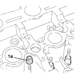
1. Remove the single-acting valve (1a) for the lubrication circuit.
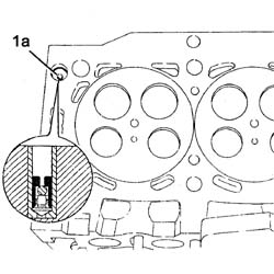
- De-carbonize and clean the valve seats and ducts.
- Clean any residues of the old gasket from the lower cylinder head plane. 1. Check that the cylinder head plane flatness is within the recommended values.
1. Check that the cylinder head plane flatness is within the recommended values.
| Lower plane planarity (mm) | |
|---|---|
| 0.05 |
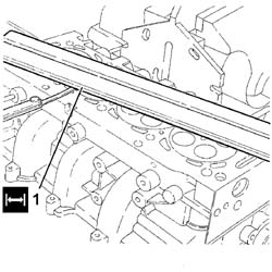
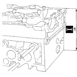
1. Check that the height of the head is within the recommended values.
If necessary, reface the lower cylinder head plane. The maximum value that can be removed is 0.4 mm of material in relation to the nominal value of the cylinder head height (manufacturer''s figure).
| Cylinder head height (manufacturer''s figure) mm | |
|---|---|
| 133 ± 0.05 |
If the head support surface is refaced, the excess value for the values must be corrected.
This correct involves fitting special valves, available as spares, with an undersize height.
- If necessary, replace the valve guides, carry out
Op. 1016E14 VALVE GUIDES IN SINGLE CYLINDER HEAD - REPLACE DURING OP. 1016E10
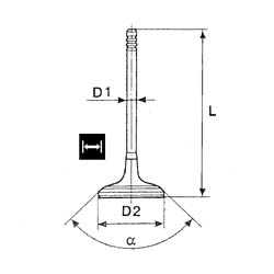
- Check that the valve stem does not show signs of grooves or seizing.
- Check that the diameter of the valve stems corresponds to the recommended figures; if not, replace the worn valves.
| Inlet and exhaust valve stem diameter (mm) | |
|---|---|
| - ÷ - |
- Check that the diameter of the valve head corresponds to the recommended figures; if not, replace the valves.
| Inlet and exhaust valve outer diameter (mm) | |
|---|---|
| - ÷ - |
- Check that the height of the valve corresponds to the recommended figures; if not, replace the valves.
| Valve guide inner diameter (mm) | |
|---|---|
| - ÷ - |
1. Check that the valve guide inner diameter and the clearance with the valve are within the recommended values, or else the valve guide must be replaced.
- If necessary, replace the valve guides, refer to
Op. 1016E14 VALVE GUIDES IN SINGLE CYLINDER HEAD - REPLACE DURING OP. 1016E10
| Valve guide inner diameter (mm) | |
|---|---|
| 6.022 ÷ 6.040 |
| Valve stem - valve guide clearance (mm) | |
|---|---|
| 0.14 ÷ 0.082 |
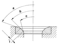
- Grind the valve seats if the valves and the valve guides are being replaced.
| Upper band taper "a" | |
|---|---|
| - ± - |
| Contact band taper "b" with valve |
|---|
| Lower band taper "c" |
|---|
| Contact band width "I" with valve (mm) |
|---|
- When the operation is completed, clean the valve seats thoroughly.
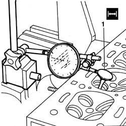
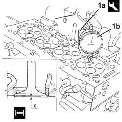
1, Fit the inlet and exhaust valves in their seats and, using the tool (1a), complete with dial gauge (1b), check that the projection for each valve is within the recommended figures.
Take four measurements on opposite diameters and take the average value.
| Inlet valve projection mm | Validity |
|---|---|
| 0,05 |
| Exhaust valve projection | Validity |
|---|---|
| 0.05 |
- Using special equipment, check that the valve spring specifications are within the recommended values; if this is not the case, replace the components that do not comply.
| Inlet valve spring height (mm) | Under a load of daN | |
|---|---|---|
| - ± - |
| Exhaust valve spring height (mm) | Under a load of daN | |
|---|---|---|
| - ± - |
- Fit the valves, injectors and heater plugs, then carry out a valve leakage test.
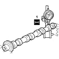
1. Check that the cam lifts for the inlet side and exhaust side camshafts are within the recommended values.
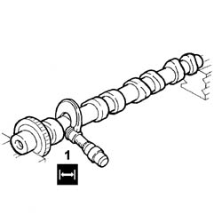
1. Check that the diameter of the inlet side and exhaust side camshaft bearings are within the recommended values.
1. Temporarily fit the inlet and exhaust side camshafts.
2. Temporarily fit the intake manifold/head cover.
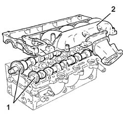
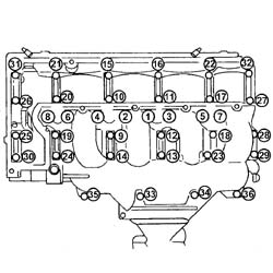
Tighten studs 1 to 8 to the recommended torque following the order illustrated in the diagram.
| Value daNm | Fastening | Component | dia | |
|---|---|---|---|---|
| (-) 1 | Studs | SINGLE CYLINDER HEAD - R.R. and Replace gasket |
Use a USAG 235 E6 spanner for tightening the studs
- carry out a pre-tightening cycle (from 9 to 36) then a tightening cycle (from 9 to 36) to the recommended torque on the intake manifold/head cover fixing bolts, following the order illustrated in the diagram;
| Value daNm | Fastening | Component | dia | |
|---|---|---|---|---|
| (-) 0.5 | Bolt pre-tightening | SINGLE CYLINDER HEAD - R.R. and Replace gasket |
| Value daNm | Fastening | Component | dia | |
|---|---|---|---|---|
| (-) 1.0 | Botl tightening | SINGLE CYLINDER HEAD - R.R. and Replace gasket |
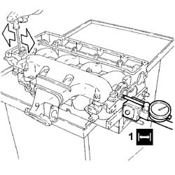
1. Check that the endfloat of the camshafts is within the recommended values
| End float (mm) | |
|---|---|
| - ± - |
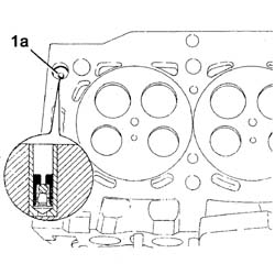
1. Fit the single-acting valve for the lubrication circuit (1a).
- Fit the inlet and exhaust valves in the valve guides, then fit the tool for retaining the valves
| Description | Code | Function | |
|---|---|---|---|
| Valve retaining base | 1.860.804.000 | Valve spring compression |
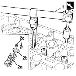
1. Fit the spring support lower cotter-seals and position the tool for compressing the valve springs;
2. Refit the springs (2a), upper cotters (2b) and caps (2c).
| Description | Code | Function | |
|---|---|---|---|
| Lever | 1.860.644.000 | Valve spring compression |
- Fit the rocker-tappet assemblies.
- fit the bracket for the throttle control lever.
1. Fit the throttle shaft (1a) complete with control lever (1b).
2. Rotate the shaft, position the throttle (2a) and tighten the fixing bolts (2b). Repeat the operation for all the intake manifolds.
- Position the common rail manifold in place and tighten the fixing bolts and the nut.
1. Place the bracket (1a) in position and tighten the fixing bolts (1b).
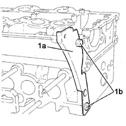
1. Place the bracket (1a) in position and tighten the fixing bolts (1b).
2 Remove the cylinder head support tool.
| Description | Code | Function | |
|---|---|---|---|
| Support | 1.860.170.000 | Cylinder head support |
Parts & tools for this job For 2002 Fiat Ulysse
- PARTEngine gasket setSearch: Fiat Ulysse 2002 engine gasket set
- TOOLTorque wrenchSearch: 3/8 inch torque wrench
- TOOLFeeler gauge setSearch: feeler gauge set
Links open Amazon search results in a new tab. As an Amazon Associate I earn from qualifying purchases.