| In-vehicle Repair Special Tool(s) | | Universal flange holding wrench 205-072 (15-030A) | | | Adjusting tool, camshaft TDC setting 303-376 (21-162B) | | | Adjusting pin, crankshaft TDC setting 303-574 (21-163) | | | Pliers, spark plug connector 303-622 (21-226) | General Equipment Trolley jack Wooden block Materials Name Specification Silicone grease, spark plug connector seal A969-M1C171-AA Never Seeze ESE-M1244-A Removal | | -
General - Make a note of the radio keycode.
- Make a note of the preset radio stations.
- Due to special model variants, some job steps do not apply to all vehicles. These are clearly marked in the text.
- If necessary, cut the cable ties and renew them on installation.
| | | -
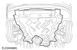
Detach the engine undershield (nine bolts) (if present). | | | -
Detach the right-hand lower wheel housing cover (shown with the front wheel removed). | | | -
NOTE:Mark the drive belt running direction. Remove the drive belt. - Loosen the coolant pump pulley bolts.
- Slacken the drive belt by turning clockwise and remove it.
- Detach the coolant pump pulley.
- Remove the drive belt idler pulley.
| | | -
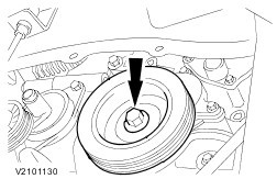
Remove the crankshaft pulley/vibration damper. | | | -
CAUTION:Always remove the timing belt cover to avoid damaging the timing belt. Remove the lower timing belt cover. | | | -
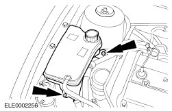
Detach the coolant expansion tank and lay it to one side. - Detach the cruise control system cable from the coolant expansion tank (if present).
| | | -
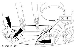
CAUTION:Insert the wooden block between the oil pan and the trolley jack. Position the trolley jack with the wooden block under the oil pan and raise so that the front engine mounting is free from load. | | | -
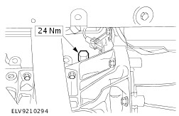
NOTE:Mark the installation position of the engine mounting. Remove the front engine mounting. | | | -
NOTE:This step only applies to vehicles with liquid propane gas (LPG) drive. | | | -
Detach the bracket for the power steering fluid line from the engine lifting eye. | | | -
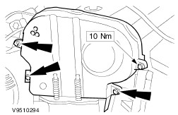
NOTE:Leave the timing belt cover in its installation position. Remove the upper timing belt cover. | | | -
Detach the centre timing belt cover/front engine mounting bracket. - Remove the timing belt upper cover.
| | | -
Unclip the accelerator cable and cruise control system cable from the cylinder head cover. | | | -
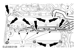
CAUTION:Do not pull the cables when removing the spark plug connectors. If necessary, remove the ignition cable from the ignition coil to avoid kinking the cable. Turn the spark plug connector slightly before removing to loosen the seal. CAUTION:Pull off the spark plug connectors in line with the spark plugs (for angled spark plug connectors use Special Tool 303-622). CAUTION:The spark plugs must be removed in order to adjust the valve timing. Remove the spark plugs and the cylinder head cover. - Pull off the spark plug connectors.
- Remove the bolts.
- Remove the spark plugs.
| | | -
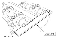
CAUTION:Essential in order to adjust the valve timing. Turn the engine to ignition position for cylinder no. 1 and insert the special tool into the camshaft. | | | -
Slacken the timing belt. - Loosen the bolt and slacken the timing belt tensioner by turning clockwise.
- Unscrew the bolt four turns and unhook the timing belt tensioner.
| | | -
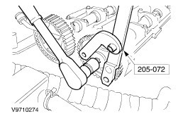
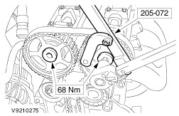
Release the camshaft timing pulleys using Special Tool 205-072 to prevent movement. | Installation | | -
Release the camshaft timing pulleys using Special Tool 205-072 to prevent movement. | | | -
NOTE:Do not tighten the bolts. The camshaft timing pulleys must be free to turn on the camshafts. Turn the camshafts to ignition position for cylinder no. 1 and insert the special tool into the camshafts. | | | -
Set the crankshaft to TDC for cylinder no. 1. | | | -
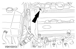
Remove the blanking plug and fully screw in the special tool. | | | -
CAUTION:Use a new timing belt. CAUTION:Do not kink the timing belt (bend diameter must not be less than 35 mm). CAUTION:Do not turn the crankshaft. If necessary check whether the crankshaft is touching Special Tool 303-574. NOTE:Version with lower idler pulley shown (built until approx. 01/99). NOTE:The clip of the timing belt tensioner must not be hooked into the pressed steel cover. Fit the new timing belt (shown on removed engine). - Starting at the crankshaft timing pulley and working anti-clockwise, fit the timing belt. Pull the belt tight as you proceed.
| | | -
CAUTION:Use a new timing belt. CAUTION:Do not kink the timing belt (bend diameter must not be less than 35 mm). CAUTION:Do not turn the crankshaft. If necessary check whether the crankshaft is touching Special Tool 303-574. NOTE:Version without lower idler pulley shown (built from approx. 01/99). NOTE:The clip of the timing belt tensioner must not be hooked into the pressed steel cover. Fit the new timing belt (shown on removed engine). - Starting at the crankshaft timing pulley and working anti-clockwise, fit the timing belt. Pull the belt tight as you proceed.
| | | -
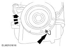
CAUTION:Tension the timing belt by turning anticlockwise. NOTE:Incorrect timing belt tension results in incorrect valve timing and timing belt noise. Tension the timing belt. - Hook the timing belt tensioner into the pressed steel cover and screw in the bolt loosely.
- Tension the timing belt by turning the tensioner anticlockwise until the arrow aligns with the mark.
| | | -
CAUTION:Do not tighten the camshaft timing pulley bolts against Special Tool 303-376; use Special Tool 205-072 to prevent movement. NOTE:The crankshaft must remain at TDC. Tighten the camshaft timing pulley bolts. | | | -
Unscrew and remove Special Tool 303-574. | | | -
Remove Special Tool 303-376 from the camshafts. | | | -
NOTE:Turn the engine at the crankshaft by two revolutions in the direction of rotation. Check the valve timing by inserting the special tool. Correct adjustment if necessary. - Screw in Special Tool 303-574 and ensure that the crankshaft is touching it.
- Insert Special Tool 303-376 into the camshafts; if necessary loosen the timing pulleys, correct the camshaft setting and re-check.
- Detach the special tools.
| | | -
Screw in the blanking plug. | | | -
CAUTION:Use a blunt object (e.g. a plastic cable tie) to apply the silicone grease to avoid damaging the spark plug connector seal. CAUTION:Push on the spark plug connectors in line with the spark plugs. NOTE:Coat the inside of the spark plug connectors with silicone grease to a depth of 5-10 mm. Install the cylinder head cover and spark plugs. - Coat the spark plug threads with Never Seeze.
- Screw in the spark plugs.
- Screw in the cylinder head cover bolts in two stages.
- Push on the spark plug connectors until they engage.
| | | -
Clip the accelerator cable and cruise control system cable to the cylinder head cover. | | | -
NOTE:Fit the upper timing belt cover together with the centre timing belt cover. Attach the centre timing belt cover/front engine mounting bracket. | | | -
NOTE:Check the seating of the upper timing belt cover gasket and correct if necessary. Fit the upper timing belt cover. | | | -
Attach the bracket for the power steering fluid line to the engine lifting eye. | | | -
NOTE:This step only applies to vehicles with liquid propane gas (LPG) drive. | | | -
NOTE:If the engine mounting cannot be easily reinstalled, the engine must be aligned to the subframe. Install the front engine mounting. | | | -
Fit the coolant expansion tank. - Attach the cruise control system cable to the coolant expansion tank (if present).
| | | -
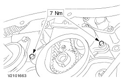
NOTE:Ensure correct seating of the lower cover in the centre cover. Fit the lower timing belt cover. | | | -
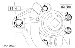
Install the crankshaft pulley/vibration damper. | | | -
NOTE:Ensure correct seating. NOTE:Observe running direction marking on used drive belts. NOTE:Screw the bolts fully home but do not tighten them. Install the drive belt. - Fit the drive belt idler pulley.
- Install the coolant pump pulley.
- Tension the belt tensioner clockwise and lie it against the drive belt.
- Tighten the coolant pump pulley bolts.
| | | -
Attach the right lower wheel housing cover (shown with the front wheel removed). | | | -
Attach the engine undershield (nine bolts) (if removed). | | | -
Standard finishing operations: - Connect the battery ground cable.
- Check the fluid levels and correct if necessary.
- Check the routing of the vacuum hoses and wiring and secure with cable ties.
- Reprogram the preset radio stations.
- Carry out a road test to enable the PCM to collect data.
| | |