| Disassembly and Assembly of Subassemblies Special Tool(s) | | Remover, Bearing (Main Tool) 205-295 (15-050A) | | | Collet for 205-295 308-195 (16-060) | | | Collet for 205-295 308-196 (16-061) | | | Support Plate, Gear Removal 308-198 (16-063) | Materials Name Specification Manual transmission fluid WSD-M2C200-C Disassembly All vehicles | | -
CAUTION:The inner synchronizer ring and the synchronizer cone must be handled very carefully. NOTE:The design and assembly procedure for the third gear single synchronizer are the same as for fourth gear. Refer to the table in Specifications if synchronizer parts have to be newly installed. NOTE:If any new installation of bearings, shafts or the transaxle housings is necessary, the transaxle must be shimmed. NOTE:General view of the input shaft. For additional information, refer to Manual Transaxle in this section. NOTE:Using a suitable press, remove the gear wheels. NOTE:Use vise jaws protectors for all operations in a vise. Secure the input shaft in a vise. | | | -
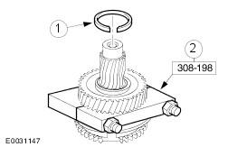
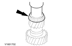
Using the special tools, remove the clutch housing roller bearing. | | | -
Using the special tools, remove the transaxle housing roller bearing. | | | -
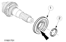
Using the special tool, remove the fifth gear wheel. - Discard the snap ring.
- Remove the fifth gear wheel.
| | | -
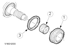
Remove the fourth gear wheel. - Remove the fourth gear wheel.
- Remove the needle roller bearing.
- Remove the synchronizer ring.
| | | -
Remove the third and fourth gear synchronizer assembly. - Discard the snap ring.
- Remove the synchronizer assembly.
| | | -
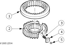
NOTE:Mark the position of the selector ring in relation to the synchronizer hub to aid installation. Components are paired. NOTE:Remove the selector ring carefully. The detent balls are spring loaded. Disassemble the third and fourth gear synchronizer assembly. - Remove the selector ring.
- Remove the gear synchronizer hub.
- Remove the compression springs.
- Remove the blocker bars.
- Remove the detent balls.
| Vehicles built up to 08/2001 | | -
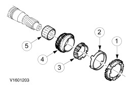
Remove the third gear wheel. - Remove the outer synchronizer ring.
- Remove the synchronizer cone.
- Remove the inner synchronizer ring.
- Remove the third gear wheel.
- Remove the needle roller bearing.
| Vehicles built 08/2001 onwards | | -
Remove the third gear wheel. - Remove the synchronizer ring.
- Remove the third gear wheel.
- Remove the needle roller bearing.
| Assembly All vehicles | | -
NOTE:Using a suitable press, install the gear wheels. NOTE:Use vise jaws protectors for all operations in a vise. NOTE:If installing new roller bearings, do not lubricate the bearings. | | | -
Using a suitable length of tube, install the clutch housing roller bearing. | Vehicles built up to 08/2001 | | -
Install the third gear wheel. - Install the needle roller bearing.
- Install the third gear wheel.
- Install the inner synchronizer ring.
- Install the synchronizer cone.
- Install the outer synchronizer ring.
| Vehicles built 08/2001 onwards | | -
Install the third gear wheel. - Install the needle roller bearing.
- Install the third gear wheel.
- Install the synchronizer ring.
| All vehicles | | -
NOTE:Observe the markings. Assemble the third and fourth gear synchronizer assembly. - Insert the compression springs.
- Insert the synchronizer bar and detent balls by pressing against the spring pressure.
- Install the selector ring the right way round and slide it on.
| | | -
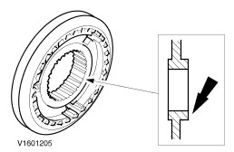
Make sure the third and fourth gear synchronizer assembly is installed with the annular groove facing the small collar. | Vehicles built up to 08/2000 | | -
NOTE:Install the synchronizer hub with the large collar facing outwards. NOTE:Install a new snap ring. Install the third and fourth gear synchronizer assembly. - Install the synchronizer assembly.
NOTE:The snap ring thickness is 2.0 mm. - Install the snap ring.
| Vehicles built 08/2000 onwards | | -
NOTE:Install the synchronizer hub with the large collar facing outwards. NOTE:Install a new snap ring. Install the third and fourth gear synchronizer assembly. - Install the synchronizer assembly.
NOTE:The snap ring thickness is 2.5 mm. - Install the snap ring.
| All vehicles | | -
Install the fourth gear wheel. - Install the synchronizer ring.
- Install the needle roller bearing.
- Install the fourth gear wheel.
| | | -
NOTE:Install a new snap ring. Using a suitable length of tube, install the fifth gear wheel. | | | -
Using a suitable length of tube, install the transaxle housing roller bearing. | |