| Disassembly Special Tool(s) | | Slide Hammer 205-047 (15011) | | | Universal Flange Holding Wrench 205-072 (15030A) | | | Pliers, Valve Shim 303-196 (21107) | | | Socket, Cylinder Head Bolt 303-392 (21167) | | | Locking Tool, Flywheel 303-393 (21168) | | | Mounting Stand 303-435 (21187) | | | Mounting bracket for 303-435 303-435-06 (21031B) | | | Mounting plate for 303-435-06 303-435-14A (21212A) | | | Socket, Spark Plug 303-499 (21202) | | | Pliers, Spark Plug Connector 303-622 (21226) | | | Adapter for 205-047 303-633 (21227) | General Equipment Disassembly All Vehicles | | -
Secure the engine to the assembly stand. - Attach the special tools to the engine.
| | | -
Drain the engine oil and detach the oil filter. | Vehicles without air conditioning | | -
Detach the drive belt tensioner. | All vehicles | | -
Remove the upper timing belt cover. | | | -
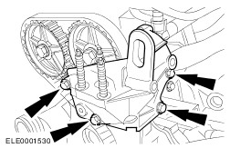
Detach the engine mounting bracket. | Vehicles built up to 12/2000 | | -
Detach the cylinder head cover top plate (if present). | | | -
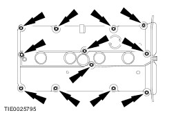
CAUTION:The cylinder head cover gasket cannot be renewed separately. To avoid damaging the gasket when removing it, lift off the cylinder head cover directly upwards. CAUTION:Do not pull on the cable when pulling off the spark plug connector. If necessary remove the ignition coil plug to avoid bending the cable. Turn the spark plug connector slightly before pulling it off in order to loosen the seal. CAUTION:Pull off the spark plug connector in a straight movement. Remove the cylinder head cover. - Remove the high-tension lead clip.
- Disconnect the HT leads from the spark plugs.
- Use Special Tool 303-622 for angled spark plug connectors.
- Pull out the plug of the cylinder head temperature (CHT) sensor.
- Unscrew and remove the nuts.
| Vehicles built up to 12/2000 | | -
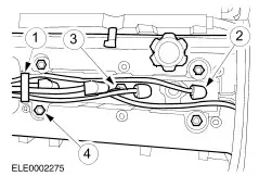
CAUTION:Do not pull the cable when removing the spark plug connector. If necessary remove the ignition coil plug to avoid bending the cable. Turn the spark plug connector slightly before removing to loosen the seal. CAUTION:Pull off the spark plug connector in a straight movement. Disconnect the spark plug electrical connectors and unclip the wires from the valve cover. | | | -
Disconnect the cylinder head temperature (CHT) sensor electrical connector. | All vehicles | | -
Remove the crankshaft pulley/vibration damper. | | | -
Detach the lower timing belt cover. | Timing belt tensioner with cam | | -
Slacken and remove the timing belt. | | | -
Detach the timing belt tensioner. | Timing belt tensioner with slot | | -
Slacken and remove the timing belt. | | | -
Detach the timing belt tensioner. | Vehicles built 09/2003 onwards | | -
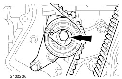
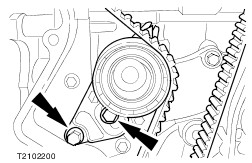
Remove the timing belt. - Tension the timing belt tensioner by turning and lock it with the special tool.
| | | -
Remove the timing belt tensioner. | All vehicles | | -
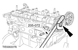
Remove the camshaft timing pulleys. - Hold in place using the special tool.
- Discard the retaining bolts.
| | | -
Detach the crankshaft timing pulley. | | | -
Detach the inner timing belt cover. | | | -
NOTE:Tightening sequence. NOTE:Keep the bearing caps in order for reassembly. Identification numbers are provided on the outer face of the camshaft bearing caps. Remove the camshafts. - Slacken each bolt of the camshaft bearing cap by one turn until the camshaft is released.
- Detach the camshaft bearing cap.
- Remove the camshaft oil seal.
| Vehicles built up to 01/2001 | | -
NOTE:Keep the valve tappets and the valve adjusting shims in order for reassembly. Remove the valve tappets and valve adjusting shims using the special tool. | Vehicles built 01/2001 onwards | | -
NOTE:Keep the valve tappets in order for reassembly. Remove the valve tappets using the special tool. | All vehicles | | -
Detach the crankcase ventilation hose. | | | -
Remove the three lower inlet manifold bolts from the cylinder block and detach the oil dipstick tube. - Unclip the knock sensor (KS) plug from the oil dipstick tube.
| | | -
CAUTION:The cylinder head must have cooled to below 30°C before removal. CAUTION:Place the cylinder head on a soft support. NOTE:Tightening sequence. Detach the cylinder head. - Remove the cylinder head bolts using the special tool.
| | | -
CAUTION:Do not damage the coolant pump impeller. Remove the coolant pump. | | | -
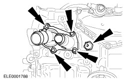
Detach the thermostat housing and the oil pressure switch. | | | -
Detach the crankcase ventilation and the KS. | Vehicles built up to 11/1999 | | -
CAUTION:Remove oil pan by pulling it downwards to prevent oil deposits or abraded particles from entering the engine. Detach the oil pan. | Vehicles built from 12/1999 | | -
Drain the engine oil and remove the oil pan bolts (shown with engine installed in the vehicle). - Remove the drain plug.
- Remove the oil pan bolts.
| | | -
CAUTION:To avoid damaging the sealing surfaces, only use the special tool described to remove the oil pan. Do not use a chisel or a screwdriver for removal. Detach the oil pan. - Attach the special tools and lock against the oil pan.
- Release the oil pan from the cylinder block by several blows.
| All vehicles | | -
Detach the oil intake pipe and the oil pump with gasket. - Drive the oil seal out of the oil pump on a flat surface.
| Vehicles with manual transmission | | -
CAUTION:Loosen the bolts by two turns until the clutch pressure plate is released. Using the special tool, immobilize the flywheel and remove the clutch. | | | -
Detach the flywheel (immobilized by the special tool). | Vehicles with automatic transmission | | -
Detach the drive plate (immobilised by the special tool). | All vehicles | | -
Remove the crankshaft position (CKP) sensor. | | | -
Detach the rear crankshaft oil seal housing and the crankshaft position (CKP) sensor mounting. | | | -
Detach the cylinder block with crank gear from the assembly stand (short block). - Detach the special tools from the cylinder block.
| |