| Removal Special Tool(s) | | Remover, Halfshaft 204-226 (16-092) | | | Adaptor for 204-226 204-226-01 (16-092-01) | | | Slide Hammer 205-047 (15-011) | | | Separator, Ball Joint 211-020 (13-006) | | | Support Bar, Engine 303-290A (21-140) | | | Adaptor for 303-290A (21-140) 303-290-01 (21-140-01) | | | Adaptor for 303-290A (21-140) 303-290-02 (21-140-02) | | | Adaptor for 303-290A (21-140) 303-290-03 (21-140-03) | | | Adaptor for 303-290A (21-140) 303-290-08 (21-140-08) | General Equipment Securing straps Transmission jack Wooden block Removal | | -
NOTE:The locations of engine mountings and engine support insulators are given from the transaxle to the engine. Move the selector lever to "D" position. | | | -
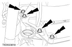
Remove the battery tray. - Detach the connector from the battery tray.
- Remove the retaining bolts.
- Detach the wiring harness from the battery tray.
| | | -
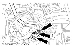
Remove the air cleaner housing. - Disconnect the mass air flow (MAF) sensor electrical connector.
- Detach the crankcase ventilation hose from the air intake cleaner.
- Detach the intake hose from the throttle body.
| | | -
Remove the air cleaner intake pipe. | | | -
Disconnect the electrical connectors from the selector lever assembly. - Disconnect the transmission range (TR) sensor electrical connector.
- Disconnect the automatic transaxle electrical connector.
| | | -
Detach the selector lever cable from the selector lever assembly. | | | -
Disconnect the turbine shaft speed (TSS) sensor electrical connector. | | | -
Loosen the strut and spring assembly top mount nuts by five turns on both sides. | | | -
Detach the oil filler pipe and selector lever cable retaining bracket from the transaxle. | | | -
Remove the engine right-hand support insulator. | | | -
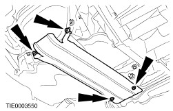
Remove the ground cover heat shield. | | | -
CAUTION:Excessive bending of the flexible exhaust pipe may cause damage resulting in failure. Support the flexible exhaust pipe with a support wrap or suitable splint. Remove the flexible exhaust pipe. | | | -
CAUTION:Leave the tie-rod end retaining nut in place to protect the ball joint stud. Loosen the left-hand tie-rod end retaining nut. | | | -
CAUTION:Protect the ball joint seal using a soft cloth to prevent damage. Using the special tool, detach the tie-rod end from the wheel knuckle. | | | -
Detach the lower arm from the wheel knuckle on both sides. | | | -
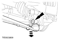
Remove the right-hand halfshaft center bearing cap. - Discard the center bearing cap and locknuts.
| | | -
CAUTION:Support the halfshaft. The inner joint must not be bend more than 18 degrees. The outer joint must not be bent more than 45 degrees. CAUTION:Do not damage the halfshaft oil seal. NOTE:Plug the transaxle to prevent oil loss or dirt ingress. Detach the right-hand halfshaft from the transaxle and secure it to one side. - Allow the oil to drain into a suitable container.
| | | -
CAUTION:Support the halfshaft. The inner joint must not be bend more than 18 degrees. The outer joint must not be bent more than 45 degrees. CAUTION:Do not damage the halfshaft oil seal. NOTE:Plug the transaxle to prevent oil loss or dirt ingress. Using the special tools, detach the left-hand halfshaft from the transaxle and secure it to one side. - Discard the snap ring from the stub shaft.
- Allow the oil to drain into a suitable container.
| | | -
Disconnect the output shaft speed (OSS) sensor electrical connector. | | | -
CAUTION:Do not loosen the connecting fitting from the transaxle housing. Detach the oil cooler pipes from the transaxle. | | | -
Install the special tools. | | | -
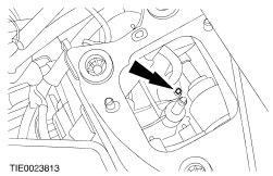
Remove the engine and transaxle rear mounting. | | | -
Using the special tools, lower the engine and transaxle assembly. | | | -
Remove the engine and transaxle mounting rear retaining bracket. | | | -
Detach the transaxle wiring harness from the transaxle. - Disconnect the electrical connectors.
| | | -
Remove the starter motor retaining bolts. | | | -
Remove the transaxle upper retaining bolts. | | | -
Remove the oil filler pipe. | | | -
NOTE:The engine must be turned to access the torque converter retaining nuts. Detach the torque converter from the flywheel (four nuts). - Remove the cover (if equipped).
| | | -
Detach the starter motor electrical connectors. | | | -
Remove the starter motor. | | | -
Remove the transaxle left-hand retaining bolts. | | | -
Remove the transaxle right-hand retaining bolts. | | | -
CAUTION:Make sure the torque converter is secured. NOTE:Make a note of the position and numbers of the dowels at the engine flange, to aid installation. Remove the transaxle. | | |