| Assembly Special Tool(s) | | Universal flange holding wrench 205-072 (15-030A) | | | Aligner, clutch disk 308-205 (16-067) | | | Timing pin, crankshaft TDC position 303-193 (21-104) | | | Aligner/installer, crankshaft front oil seal 303-318 (21-148A) | | | Alignment tool, camshaft alignment 303-376 (21-162B) | | | Socket, cylinder head bolts 303-377 (21-164) | | | Locking tool, flywheel 303-393 (21-168) | | | Aligner, crankshaft rear oil seal 303-513 (21-217) | | | Angle gauge, bolt tightening 303-174 (21-540) | | | Timing pin, injection pump timing 303-018 (23-019) | | | Timing pin, crankshaft position sensor (CKP sensor) 310-057 (23-049) | General Equipment Micrometer Feeler gauge Internal gauge Piston ring compressor Dial gauge fixture Dial gauge Materials Name Specification Sealer SM-4G-9112-F/G Plastigage Engine oil 5W-30 WSS-M2C912-A1 Assembly | | -
Clean all mating faces and reusable parts thoroughly and check them for damage. | | | -
Clean the oil splash nozzles for piston cooling and the oilways. | | | -
NOTE:The bearing cap numbering begins at the timing belt end, to which the arrows also point. Install the crankshaft. - Lubricate the main bearing journals, the bearings shells and the thrust half rings with engine oil .
- Insert the thrust half rings into main bearing no. 3 with their lubricating grooves facing outwards.
- Fit the crankshaft main bearing caps with their associated bearing shells.
| | | -
NOTE:The connecting rod numbering starts at the timing belt end. The arrow on the piston crown points towards the timing belt end. Install the pistons. - Lubricate the pistons and cylinder liners with engine oil .
- Distribute the piston ring gaps evenly around the circumference. The same applies to the elements of the oil scraper ring.
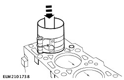
- Press the pistons into the cylinders using the handle of a hammer while guiding the connecting rods onto the big-end bearing journals.
- Fit the appropriate bearing shells, clean and dry, in the connecting rods.
| | | -
Fit the oil intake pipe with its bracket. NOTE:Make sure that the O-ring is seated correctly. - Fit the oil intake pipe, using a new O-ring.
- Fit the bracket.
| | | -
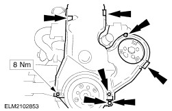
Attach the timing cover. - Fit the timing cover with a new gasket and new rubber oilway seals.
NOTE:The mating face of the timing cover must be flush with the lower edge of the cylinder block (tolerance +/- 0,1 mm). - Center the timing cover with the aligner and installer.
- Tighten the bolts.
| | | -
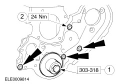
CAUTION:Fit the oil seal without lubrication. Fit the crankshaft front oil seal using the crankshaft pulley/vibration damper bolt. | | | -
CAUTION:Carry out step 16 immediately after step 15 to prevent the oil seal from contracting. NOTE:Make sure that the O-ring in the timing pulley is in perfect condition. It must be possible to insert the roll pin in the crankshaft bore. Fit the crankshaft timing pulley. - Carefully slide on the timing pulley as far as its stop.
| | | -
CAUTION:The oil pan bolts must be tightened within 20 minutes of applying the sealer. Apply sealer to the cylinder block mating face intersections. | | | -
Fit the oil pan. - Fit the oil pan with a new gasket and screw in the bolts (x14) finger tight.
- Align the oil pan so that it is flush.
| | | -
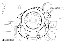
CAUTION:Fit the oil seal without lubrication. The support ring will fall out by itself when the crankshaft oil seal carrier is fitted. Do not remove it beforehand. Fit the crankshaft rear oil seal carrier. - Locate the new crankshaft oil seal carrier with the integrated oil seal and the bolts in position.
- Fit the aligner and center the oil seal carrier on the crankshaft.
| | | -
CAUTION:If the special tool cannot be removed, the oil pan must be realigned. Tighten the bolts of the crankshaft rear oil seal carrier. - Remove the aligner/installer.
| | | -
Tighten the oil pan bolts (x14). | | | -
Center the clutch disk on the clutch pressure plate. | | | -
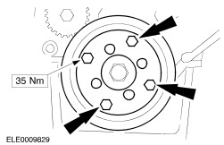
Fit the clutch pressure plate with the centered clutch disk. - Fit the clutch pressure plate in position with the centered clutch disk.
- Tighten the bolts uniformly, working diagonally.
- Remove the aligner.
| | | -
CAUTION:Use a new gasket. Fit the coolant pump. | | | -
NOTE:The lubricating grooves on the thrust plate must face outwards. Fit the auxiliary shaft. - Coat the auxiliary shaft, the bearing bush in the cylinder block and the retaining plate with 5W-30 engine oil .
- Fit the auxiliary shaft with the thrust plate and tighten the bolts.
| | | -
CAUTION:Use a new oil seal carrier. Fit the auxiliary shaft oil seal carrier. - Slide the auxiliary shaft oil seal carrier with the integrated oil seal and plastic fitting sleeve onto the auxiliary shaft spigot.
| | | -
Align the crankshaft and the camshaft. - Turn the crankshaft until cylinder no. 1 is at TDC.
- The crankshaft and camshaft must not be turned any more.
| | | -
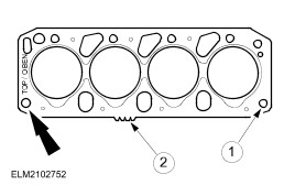
NOTE:Use a new cylinder head gasket. "TOP/OBEN" mark. Fit the cylinder head gasket. - Check that the guide sleeves are correctly seated.
- Check that the thickness markings correspond to the piston protrusion measurement.
| | | -
NOTE:The turbocharger oil return hose must be connected when the cylinder head is fitted. Fit the cylinder head. | | | -
CAUTION:Use new unoiled cylinder head bolts. It is not permitted to retighten the cylinder head bolts. Tighten the cylinder head bolts. - Tighten the cylinder head bolts in two stages in the specified sequence using a socket wrench.
| | | -
CAUTION:For stage 3, first slacken the cylinder head bolt, then tighten it to the specified torque and angle in accordance with the tightening sequence. Then move on to the next bolt. NOTE:It is not permitted to retighten the cylinder head bolts. Wait three minutes and then tighten the cylinder head bolts. - Stage 3: undo the bolt 180 degrees.
- Stage 4: tighten the bolt to 70 Nm.
- Stage 5: tighten the bolt through 120 degrees.
| | | -
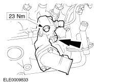
CAUTION:Use a new gasket. Attach the thermostat housing. | | | -
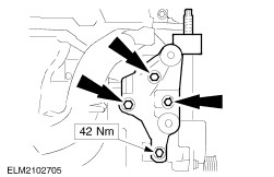
Attach the bracket of the engine mounting and power steering pump. - Connect the coolant hose.
- Bracket to cylinder block.
- Attach the bracket to the lifting eye.
| | | -
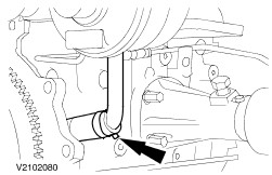
Fit the vacuum pump. - Connect the oil return hose.
NOTE:Fit the lower bolt first. - Tighten the bolts.
1. Fit the vacuum pump with a new O-ring, the bracket and the bolts. - Attach the PCV hose.
| | | -
Fit the injection pump bracket. - Attach the bracket for the boost pressure pipe.
- Attach the boost pressure pipe to the injection pump.
- Fit the bracket (two bolts/three nuts).
| | | -
Fit the fuel filter with its bracket. - Fit the fuel filter and bracket in position and tighten the nuts.
- Attach the bracket for the boost pressure pipe.
- Connect the vacuum pipe to the turbocharger.
| | | -
Fit the fuel heater and the fuel pipes. - Fit the fuel heater to the bracket.
- Connect the fuel pipes to the fuel filter.
| | | -
Connect the injection pipes to the injectors and injection pump and connect the leak-off hoses. | | | -
NOTE:Hold it with the old timing belt. Fit the auxiliary shaft timing pulley. | | | -
Fit the rear timing belt covers. | | | -
NOTE:Center the bolts in the slots; do not tighten the bolts. Fit the injection pump timing pulley. | | | -
Fit the injection pump timing belt tensioner. - Compress the tensioner spring and lock it with the bolt.
| | | -
Fit the flange of the crankshaft pulley/vibration damper. | | | -
Align the camshaft. - Insert the special tool into the slot of the camshaft.
| | | -
Align the injection pump timing pulley and turn the crankshaft to TDC. - Align the injection pump timing pulley by inserting Special Tool 308-018 (23-019) through the slot in the pulley and through the hole in the injection pump housing.
- Unscrew the blanking plug from the opening in the cylinder block for setting TDC.
NOTE:Special Tool 303-193 (21-104) must be screwed in as far as it will go. The crankshaft must be resting against the timing pin. - Screw Special Tool 303-193 (21-104) into the cylinder block.
- Turn the crankshaft carefully to TDC.
| | | -
CAUTION:The camshaft timing belt and injection pump timing belt must be renewed each time they are slackened. Re-tensioning of the timing belt is not permitted. NOTE:Make sure that the belt is correctly seated. NOTE:The bolts must not be at the ends of the slots. Fit the injection pump timing belt. - Fit the new timing belt with the slack side facing the timing belt tensioner.
- Slacken the bolt of the timing belt tensioner and allow the tensioner to snap against the belt.
- Tighten the bolt of the timing belt tensioner.
- Tighten the bolts of the timing pulley.
| | | -
Install the camshaft timing belt. For additional information, refer to Timing belt in this section. | | | -
Check valve clearance and adjust if necessary. For additional information, refer to Valve Clearances in this section. | | | -
CAUTION:The setting of 10 degrees for the adjustment of the start of fuel delivery on the fuel pump must be strictly adhered to. NOTE:When using angle gauge 303-174 (21-540), make sure that the dial does not move because of the movement of the special tool. Pressure must be constantly applied to the special tool. If the setting of 10 degrees is not achieved exactly, rotate the dial completely out of the measuring range and carry out the adjustment again. Set the crankshaft to 10 degrees after TDC on cylinder no. 1. - Locate the CKP sensor bracket without the sensor in position and attach it loosely.
- Place the angle gauge on the pulley/vibration damper and set the dial to 10 degrees.
- Turn the pulley/vibration damper until the arrows on the angle gauge line up.
| | | -
Align the CKP sensor bracket. - Insert Special Tool 310-057 (23-049) in the CKP sensor bracket and center it in the hole on the flywheel.
- Tighten the bolts of the CKP sensor bracket and remove the special tool.
| | | -
Check the alignment of the CKP sensor. - Set the crankshaft to 10 degrees after TDC on cylinder no. 1 as described in the two previous steps.
| | | -
NOTE:Clean and inspect the gasket and renew it if necessary (it can be reused several times). Coat the gasket with engine oil prior to installation. Attach the cylinder head cover. | | | -
Attach the PCV hoses. - To the cylinder block.
- To the turbocharger.
| | | -
Fit the crankshaft pulley/vibration damper. | | | -
Fit the timing belt covers. | | | -
Fit the injection pump pulley and the coolant hose. | | | -
Fit the generator bracket. | | | -
Fit the generator and the drive belt tensioner pulley. - Fit the generator (two bolts).
- Fit the generator (one bolt).
- Fit the idler pulley (two bolts).
- Screw in the bolt of the tensioner pulley.
| | | -
Fit the generator drive belt and tension it. - Fit the drive belt and tension it with the adjusting bolt.
- Check the drive belt tension.
- Tighten the tensioner pulley bolt.
| | | -
Fit the oil dipstick tube with its bracket and a new O-ring. | | | -
Detach the engine from the assembly stand. | | | -
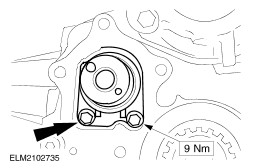
NOTE:Fill the oil pump with engine oil and lubricate the gears. Fit the oil pump. - Fit the oil pump with a new gasket and a new oil filter.
- Tighten the oil pump bolts.
- Connect the oil feed pipe to the turbocharger.
- Tighten the oil feed pipe bolt.
| | | -
Connect the coolant pipe to the oil cooler. - Connect the coolant pipe to the oil cooler.
- Tighten the bracket bolt.
| | |