
NEW MODEL – Main features and technical specifications
- Make
- Lancia
- Model
- Thesis Factory Service Manual
- Year
- 2002–2009
- Section
- Maintenance › NEW MODEL – Main features and technical specifications
NEW MODEL – Main features and technical specifications
NEW MODEL
Main features and technical specifications
The Thesis is the new top of the range Lancia
This vehicle represents the latest in technological developments in the range of luxury saloons and is part of a range of vehicles in the forefront in terms of aesthetic features.
This model is only available as a 4 door saloon in two trim levels Executive and Emblem with a choice of three different petrol engines or one Diesel engine.
The extremely high specification level with many items fitted as standard and others available on request allow the vehicle to be personalized.
The pages which follow contain the main specifications for the different engine types and a brief description of the main innovative features of the model.
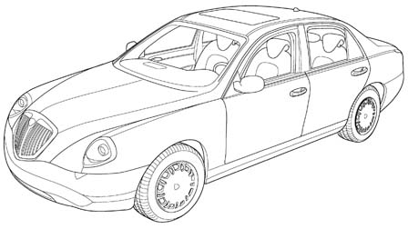
Fig. 1 - View of vehicle
DIMENSIONS
Fig. 2 - Vehicle dimensions in mm (with unladen vehicle and standard tyres)
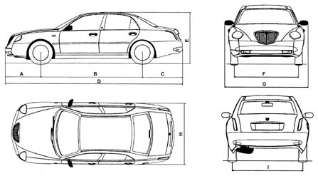
| 2.0 TB 20v | 2.4 20v - 2.4 20v CAE | 3.0 V6 CAE | 2.4 JTD | |
| A (mm) | 975 | 975 | 975 | 975 |
| B (mm) | 2803 | 2803 | 2803 | 2803 |
| C (mm) | 1110 | 1110 | 1110 | 1110 |
| D (mm) | 4888 | 4888 | 4888 | 4888 |
| E (mm) | 1465 | 1465 | 1470 | 1465 |
| F (mm) | 1569 (a) - 1573 (b) | 1569 (a) - 1573 (b) | 1569 (a) - 1573 (b) | 1569 (a) - 1573 (b) |
| G (mm) | 2002 | 2002 | 2002 | 2002 |
| H (mm) | 1830 | 1830 | 1830 | 1830 |
| I (mm) | 1541 (a) - 1545 (b) | 1541 (a) - 1545 (b) | 1541 (a) - 1545 (b) | 1541 (a) - 1545 (b) |
(a) - with 225/50 R 17 tyres
(b) - with 215/60 R 16 tyres
Luggage compartment capacity (VDA stanadards): 400 dm3
| VERSIONS | ENGINE CODE | BODYWORK VERSION |
| 2.0 TB 20v | 841E000 | 841AXA1B 03 |
| 2.4 20v | 841D000 | 841AXB1B 00 |
| 2.4 20v CAE | 841D000 | 841AXB11 04 |
| 2.4 JTD | 841C000 | 841AXD1B 02 |
| 3.0 V6 CAE | 841A000 | 841AXC11 01 |
ENGINES
The Lancia Thesis will be available with 4 different types of engine, transversely mounted at the front, with the following specifications:
| 2.0 TB 20v | |
| 841E000 1998 cm3(5 cylinders - 20 valves) 136 kW (185 CV) 5500 rpm 308 Nm (31.4 Kgm) 2200 rpm TOHC with hydraulic tappets BOSCH ME7 MPI electronic injection with variable geometry turbocharger and intercooler Electronic, static advance, integrated with the injection with one coil for each cylinder |
| 2.4 20v - 2.4 20v CAE | |
| 841D000 2446 cm3 (5 cylinders - 20 valves) 125 kW (170 CV) 6000 rpm 226 Nm (23 Kgm) 3500 rpm TOHC with hydraulic tappets MPI BOSCH ME3.1 Electronic, static advance, integrated with the injection with one coil for each cylinder |
| 2.4 JTD | |
| 841C000 2387 cm3 (5 cylinders - 10 valves) 110 kW (150 CV) 4000 rpm 305 Nm (31kgm) 1800 rpm SOHC Bosch Unijet Common Rail direct injection with variable geometry turbocharger and intercooler |
| 3.0 V6 CAE | |
| 841A000 2959 cm3 (6 cylinders - 24 valves) 158 kW (215 CV) 6300 rpm 263 Nm (26.8 Kgm) 5000 rpm TOHC per bank BOSCH ME 3.1 MPI electrnonic injection Electronic, static advance, integrated with the injection with one coil for each cylinder |
CLUTCH
The clutch is the dry, single plate, hydraulically operated type (not fitted on the 2.4 20v CAE and 3.0 V6 CAE versions because they have automatic transmission)
GEARBOX
There are 2 types of gearbox for the various engine types:
- C530.6 with 6 forward speeds plus reverse all with synchromesh for the 2.0 TB 20v, 2.4 20v and 2.4 JTD versions
- AISIN type Electronic Automatic Transmission with 5 forward speeds plus reverse for the 2.4 20v CAE and 3.0 V6 CAE versions.
Comfortonic Electronic Automatic Transmission
The 2.4 20v CAE and 3.0 V6 CAE versions are equipped with an AISIN type adapative electronically controlled automatic transmission with 5 speeds plus reverse with the possibility of dual operation: completely automatic (Full Auto) or sequential manual (Tip).
Automatic operating mode (Full Auto)
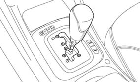
The choice of automatic operating mode is made by moving the lever (Fig. 3) in the right sector where there are 4 typical automatic gearbox positions: P, park; R, reverse; N, neutral; D, drive;
Whilst driving forwards (lever in position D) the optimum ratio is selected by the electronically controlled system depending on the speed of the vehicle, the engine load conditions, the position of the accelerator and the speed with which the actual pedal is pressed as well as the main driving conditions such as uphill, downhill, cornering and braking; in effect, in automatic mode, depending on the driving style adopted by the driver, the electronic gearbox can choose between three different programmes which range from comfortable and economy driving to sporty driving.
Sequential manual operating mode (Tip)
The gear lever can only be moved to the left sector (sequential manual) from position D; in this way the selection of the gears is entrusted to the manual intervention of the driver who, pushing the lever forwards 'goes up' a gear, and pulling it back 'changes down'.
If the request to change down causes the engine revs to go outside of the scale, this is cancelled by the electronic control unit and the driver is advised by an acoustic signal and by the flashing of the light in the instrument panel.
Fig. 3 - Automatic gear lever
BRAKING SYSTEM
The hydraulic, power assisted braking system (Fig. 4) with two, independent crossover circuits features:
- front brakes with self-ventilated discs and floating calipers with automatic play take-up;
- rear brakes with self-ventilated discs and floating calipers; the brake caliper mechanism is operated mechanically by means of an electric device;
- automatic handbrake (Electric Parking Brake);
- ABS with 4 channels and 4 sensors also capable of carrying out electronic brake distribution between the front and rear wheels (EBD), limiting slipping of drive wheels during acceleartion and traction control (ASR/MSR/TC) and dynamic stability control (ESP).
Fig. 4 - Braking system
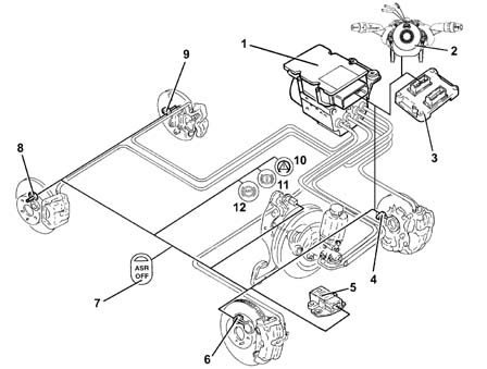
- ABS/ESP electro-hydraulic control unit
- Steering angle sensor
- Engine management control unit
- Lefr front wheel sensor
- Lateral yaw/acceleration sensors
- Right front wheel sensor
- ASR button
- Right rear wheel sensor
- Left rear wheel sensor
- ESP warning light
- EBD warning light
- ABS warning light
ESP System (Electronic Stability Program)
The ESP system is an electronically controlled vehicle stability system that operates by modulating drive torque and brking the wheels differentially if there is a loss of grip, thereby helping to return the car to its correct trajectory.
Whilst driving the vehicle is subject to lateral and longitudinal forces that can be controlled by the driver as long as the tyres hold the road well; when the road holding goes below the minimum level, the vehicle starts to drift from the driver's desired path.
If the road surface is uneven (unmade roads, ice, gravel, etc.) the tyre grip is greatly reduced. In these conditions, when manoeuvres are attempted, it is possible that the vehicle may not maintain the trajectory set (oversteer, understeer).
When the sensors detect conditions that could lead to the vehicle skidding, the ESP system intervenes on the engine and the brakes producing a torque that returns the vehicle to the correct trajectory.
The ESP system comes on automatically when the vehicle is started up and cannot be switched off.
The basic components of the ESP system (Fig. 4) are:
- an electronically controlled electro-hydraulic control unit (1) that processes the signals received from the various sensors and implements the most appropriate strategy, acting on the solenoid valves and the engine control unit (3);
- a sensor (2) that detects the steering wheel rotation angle;
- four sensors (4, 6, 8, 9) that detect the rotation speed of each wheel;
- a sensor (5) that detects slewing (the rotation of the vehicle around the vertical axis);
- a sensor (5) that detects lateral acceleration (centrifugal force).
ASR slip regulation system (ASR/MSR functions)
The ASR (Anti-Slip Regulation) is an active safety system that controls the traction, through the ASR, MSR and TC functions, by cutting in automatically whenever one or both drive wheels begin to slip.
The system converses continuously with the injection control unit and ABS and detects the onset of slipping and, depending on the driving conditions, activates the following control systems:
- if one or both drive wheels tend to slip as a result of the excessive power transmitted, the ASR control unit orders the injection control unit to reduce the torque transmitted by the engine to the wheels;
- if only one drive wheel is slipping, the ASR system intervenes braking the wheel concerned (through the brake caliper) producing an effect similar to that of a self-locking differential;
- when changing down a gear sharply, the MSR system intervenes, ordering the injection control unit to reduce the engine torque thereby preventing the wheel from locking which may lead to instability, especially in poor grip conditions.
The action of the ASR system helps increase car stability and active safety during driving, particularly under the following conditions:
- wheel slip on bends of the inner wheel, due to the effect of dynamic load changes or excessive acceleration.
- too much power transmitted to the wheels, especially when the road surface is slippery.
- acceleration over loose, snow-covered or icy road surfaces.
- loss of grip on wet ground (acquaplaning).
The ASR system comes on automatically whenever the engine is started up. the system can be deactivated and activated whilst driving by pressing the button under the centre console.
Deactivating the ASR function is signalled by the LED in the actual switch coming on together with the message shown in the instrument panel display.
If there is a fault, the ASR system switches off automatically; this condition is signalled by the warning light in the instrument panel and the message in the display coming on constantly.
EPB System (Electric Parking Brake)
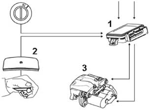
The Lancia Thesis is fitted as standard with an automatic electric handbrake EPB (Electric Parking Brake) comprising:
- an electronic control unit (1 - Fig. 5);
- an operating button (2);
- two specific brake calipers (3) each with two actuators;
- operating warning lights (in the panel);
- an additional battery and emergency button (in the boot).
Fig. 5 - EPB System Components
Automatic operation
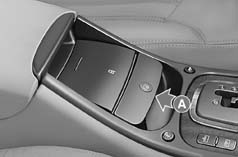
The EPB (Electric Parking Brake) switches on automatically each time the engine is switched off and is not switched off later on even if the button A (Fig. 6) in the centre console is pressed.
The parking brake can only be switched off by turning the ignition ON and pressing the button.
The parking brake also switches on automatically when the driver's door is open with the engine running. This means that the vehicle is safe when the driver leaves it with the engine running (to open a gate, garage, etc.).
Fig. 6 - EPB system activating button
Deactivating the automatic operation
If the automatic engagement of the parking brake with the engine switched off needs to be deactivated, in order to allow the vehicle to be moved manually (e.g. in a garage), the function can be deactived using the CONNECT menu or, with the ignition ON, by pressing the brake pedal and, at the same time, pressing the button (A - Fig. 6) for at least two seconds.
The handbrake warning light will flash 3 times to signal that the next time the ignition will be turned OFF the handbrake will not be applied; this manual deactivation will be cancelled the next time the engine is started up.
The deactivation of the automatic operation should be carried out before turning the ignition OFF and only with the vehicle stationary.
Manual operation
The EPB (Electric Parking Brake) can be switched on and off manually by pressing the button A (Fig. 6) in the centre console. The design of the button allows the brake to be operated quickly, even by the passenger, in cases of emergency.
This system has many advantages compared with the traditional lever:
- no force is required to switch the parking brake on or off;
- the performance of the parking brake is always optimum in all usage conditions, unlike the handbrake lever which only retains the vehicle when it is fully raised;
- the brake is controlled by electric cables and therefore all problems linked to transmission cables such as adjustments, freezing or snapping have been eliminated;
- improved safety due to the sophisticated electronically controlled system, similar to the one used by the ABS which prevents the wheels from locking if the parking brake is applied whilst driving;
- safer when children are left in the car; in effect, the brake cannot be switched off when the ignition is OFF or the key extracted.
This system also allows automatic functions that other systems do not have which are listed below:
- the handbrake warning light in the instrument panel comes on when the parking brake reaches maximum operating force and goes out when the brake is completely switched off;
- unlike conventional parking brakes, where the operating warning light already comes on for a short lever travel, in the EPB system the warning light only comes on when the vehicle is completely still;
- the operation of the brake is accompanied by a typical noise that makes the driver aware of its operation; the parking brake is completely switched on/off when this noise ends.
Brake Assistant System
For vehicles with Radar Cruise Control only (which will be described later on) a Brake Assistant system will be fitted in conjunction with the normal braking system. This system, basically consisting of an electronic control unit and a specific brake servo, is activated by the Radar Cruise Control which allows the vehicle to be braked irrespetive of the action of the driver on the brake pedal, thereby making it possible to maintain the correct distance from the vehicle in front. This is possible because the Brake Assistant node control unit controls the brake servo by means of an electro-magnet, moving the brake pump master cylinder which, as well as braking, moves the brake pedal and switches on the brake lights.
STEERING
The specifications of the Lancia Thesis steering are as follows:
- energy absorbing steering column, with manually or electrically operated axial and vertical adjustment with memory;
- energy absorbing steering wheel;
- rack and pinion hydraulic power assisted steering; hydraulic power steering with variable assistance depending on the speed (Variosteer) available on request;
- turning circle 12.2 m (12.4 m for the 2.4 JTD);
- no. of turns lock to lock: 2.24 (2.16 for the 2.4 20v CAE and 3.0 V6 CAE).
FRONT/REAR SUSPENSION
Front suspension
Front suspension (Fig. 7) independent, multilink type with 5 rods, forged aluminium, split track control arms. Coil springs, continuous damping variation telescopic shock absorbers (skyhook system) and anti-roll torsion beam.
Fig. 7 - Front suspension
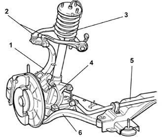
- Steering knuckle
- Upper suspension arms
- Spring/shock absorber assembly with mounting and buffer
- Fork
- Chassis
- Lower suspension arms
Rear suspension
Rear suspension (Fig. 8) independent with multiple arms, lower track control arm and 3 control rods.
Coaxial coil springs, continuous variation damping telescopic shock absorbers (skyhook system) and anti-roll torsion beam.
Fig. 8 - Rear suspension
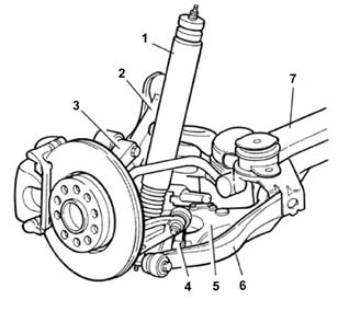
- Shock absorber
- Camber control rod
- Steering knuckle
- Vertical connecting rod
- Track control arm
- Toe in control rod
- Crossmember
Skyhook System
This system consists of six sensors capable of determining the relative speed between the bodyshell and the wheels and selecting the optimum damping force that each shock absorber should provide. The instant detection by the sensors and the compression and extension guarantee that, at any time, only the damping forces that brake the absolute vertical motion of the vehicle are produced (as if the bodyshell were attached to the sky - Skyhook - by a shock absorber).
FRONT WHEEL TOE IN
With the vehicle in running order (unladen, tyres inflated to the recommended pressure and full fuel tank) the front wheel toe in measured between the rims should be: -2 ±1 mm.
| 2.0 TB 20v | 2.4 20v 2.4 20v CAE | 2.4 JTD | 3.0 V6 CAE | |
Rims (fitted as standard) | 7Jx16 H2-39 | 7Jx16 H2-39 | 7Jx16 H2-39 | 7Jx16 H2-39 |
Tyres (fitted as standard) | 215/60 R16 (95W) 215/60 ZR16 (95W) | 215/60 R16 (95W) 215/60 ZR16 (95W) | 215/60 R16 (95W) 215/60 ZR16 (95W) | 215/60 R16 (95W) 215/60 ZR16 (95W) |
Rims (available on request) | 7Jx17 H2-41 | 7Jx17 H2-41 | 7Jx17 H2-41 | 7Jx17 H2-41 |
Tyres (*) (available on request) | 225/50 R17 (94W) 225/50 ZR17 (94W) | 225/50 R17 (94W) 225/50 ZR17 (94W) | 225/50 R17 (94W) 225/50 ZR17 (94W) | 225/50 R17 (94W) 225/50 ZR17 (94W) |
| Snow tyres | 215/60 R16 (95H) M+S | 215/60 R16 (95H) M+S | 215/60 R16 (95H) M+S | 215/60 R16 (95H) M+S |
| Inflation pressures (**) | 2.3 bar | 2.3 bar | 2.3 bar | 2.3 bar |
(*) Tyres to which chains cannot be fitted.
(**) Inflation pressures when cold, for front and rear tyres (excluding snow tyres) for both reduced load and full load.
When the tyre is warm, the pressure must be +0.3 bar higher than specified.
HEATING AND CLIMATE CONTROL
The following systems may be fitted on the Lancia Thesis (available on request for certain versions/markets):
- dual zone automatic climate control system (with controls at the front only);
- multi zone automatic climate control system (with independent controls for the rear passengers).
In both cases the climate control system has a new function that allows the occupants at the front of the vehicle (driver and passenger) to request the 'diffused' intake of air into the passenger compartment.
In this configuration, the climate control system works using three additional vents, located in the dashboard but covered by a trim and therefore not accessible, making it possible to take advantage of a different strategy for maintaining the interior temperature which offers the following advantages:
- a greater heat exchanger surface with the ambient inside the vehicle;
- lower impact speed of the air on the passengers;
- quieter air flow.
This operating system is entirely new for climate control systems and consists in the air being supplied at low speeds (around 50% less than normal operation) through additional vents.
In this way the impact speed of the air on the occupants and the noise from the air coming of the vents is considerably reduced.
The result of this combination is that the introduction of the air into the passenger compartment is virtually imperceptible with a considerable improvement in terms of comfort for the occupants.
These vents are activated through the operation of the cursor (one for each zone) for the manual opening/closing of the vents in an extra-travel position during the opening stage.
In effect, there is a switch for the end of travel position for these cursors which, if activated, sends a signal to the climate control system control unit.
When the diffused air vent is open, a visual warning by the cursor end of travel lights up.
In addition the Lancia Thesis can also be fitted (available on request for certain versions/markets) with an additional Webasto heating system.
Dual zone automatic climate control
The automatic climate control system fitted as standard on the Lancia Thesis is the dual zone type, in other words the temperature inside the passenger compartment is managed in two zones (Fig. 9): driver's zone (1) and (front and rear) passenger zone (2). The system allows the occupants to set different temperatures for each of these zones. The flow rate, however, cannot be different in the two zones.
Fig. 9 - Dual zone climate control system
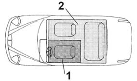
- driver's zone
- passenger zone
The dual zone automatic climate control system makes it possible to manage the temperature of the air coming out of the driver and passenger side vents separately with a maximum difference of 7 °C between the two zones and to automatically manage the air flow rate, distribution and recirculation.
For optimum control of the temperature in the two areas of the passenger compartment, in addition to the typical sensors on an automatic climate control system such as the interior, exterior and mixed air temperature sensors, this system is also equipped with a solar radiation sensor (front passenger only) capable of providing the control unit with signals proportional to the intensity and angle of the solar radiation for the two areas of the passenger compartment.
The system is also equipped with an air quality sensor (AQS) capable of detecting when a certain pollution level is exceeded and providing a signal for engaging the recirculation automatically; this has a noticeable effect on unpleasant pollutant air during town driving, driving in traffic jams and travelling through tunnels.
The climate control compressor only works if the engine is running and the outisde temperature is above 4 °C.
The outside temperature is constantly shown on the instrument panel display and if it reaches or goes below 3 °C a special icon comes on to warn the driver of the possible presence of ice.
The system is operated by the people in the front through the control panel in the centre console.
The following parameters/functions can be automatically adjusted:
- air temperature at the driver/ passenger vents (front/rear);
- air distribution to the driver/passenger vents (front/rear);
- fan speed (varies continuously);
- compressor engagement;
- recirculation.
All the functions listed can be altered manually, in other words the user can, at will, select one or more of these functions through the control panel in the centre console which is illustrated in figure 10.
Manual selections always take precendence over automatic selections and are stored until the user allows the automatic device to take over again.
The manual setting of a function does not adversely affect the control of other automatic functions.
The following parameters/functions can be set or altered manually:
- driver/passenger temperatures;
- fan speed;
- distribution in 7 positions (driver/passengers);
- diffused air distribution;
- compressor enablement;
- single zone/dual zone distribution priority (front/rear);
- MAX DEF defrosting/demisting function;
- recirculation;
- system automatic/manual management;
- heated rear windscreen;
- switching the system off;
- enabling the rear control panel.
The view of the dual zone climate control system control panel in the dashboard is illustrated below with a brief description of the control buttons (Fig. 10).
Fig. 10 - Dual zone climate control system front control panel
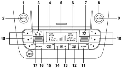
Key
- Interior temperature setting knob (driver's side).
- System automatic operation selection button (driver's side).
- Air recirculation operation button (automatic, always on or off).
- Interior temperature setting and system status display (driver's side).
- Fan speed display.
- Interior temperature setting and system status display (passenger side).
- Air conditioning compressor off button.
- Interior temperature setting knob (front passenger side).
- System automatic operation selection button (front passenger side).
- Air distribution selection buttons (front passenger side).
- Rear control panel enabling button.
- Heated rear windscreen and external rear view mirrors defrosting on/off button
- Fan speed increase button.
- Fan speed decrease button.
- Windscreen, front side windows, rearscreen, door mirrors and windscreen washer jets rapid demisting/defrosting on/off button
- Button for aligning driver's side and passenger side air distribution and temperature (front/rear).
- Interior temperature sensor.
- Air distribution selection buttons (driver's side).
Multizone automatic climate control system
There is a special version of the climate control system, available on request, that features a specific control panel for the rear passengers.
It is enabled by pressing the button 11 (Fig. 10) in the front panel.
With the rear panel enabled, the front passenger cannot alter the operating parameters in any way because the controls are disabled.
At the same time, the settings made through the rear panel are shown on the right section of the front display.
Pressing the Rear button again (LED on) reactivates the enablement of the front passenger controls (LED off).
The rear panel is illustrated below together with a brief description of the control buttons (Fig. 11).
Fig. 11 - Multizone climate control system rear control panel
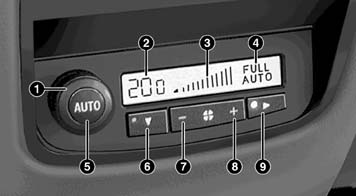
Key
- Interior temperature setting knob (rear passenger zone)
- Interior temperature setting display (rear passenger zone)
- Fan speed display
- System status display (AUTO, FULL AUTO)
- Automatic system operation selection button (rear passenger zone)
- Rear passenger footwell air distribution button
- Fan speed decrease button
- Fan speed increase button
- Rear air vent distribution button
WEBASTO ADDITIONAL HEATER
The vehicle is available, on request, with a Webasto Thermo Top C type additional heater which, by heating the engine coolant, makes it possible to reduce the time taken for the engine and the passenger compartment to warm up.
The device is connected directly to the engine cooling and fuel supply systems and basically consists of:
- a heater unit, comprising an electronic control unit, a burner and a heat exchanger; an electric pump that takes fuel from the tank and sends it to the burner; an exhaust pipe.
The Webasto heater can operate with the engine running or with it switched off and the burner is designed to run on petrol or diesel depending on the vehicle's fuel system.
DUSK SENSOR AND RAIN SENSOR
The vehicle is equipped with two sensors located under the interior rear view mirror and fitted in contact with the windscreen in the area cleaned by the windscreen wiper blades that have the task of allowing the windscreen wipers and/or side lights and dipped headlamps to come on when necessary if the user has activated the relevant controls.
Dusk Sensor
The dusk sensor regulates the automatic switching on of the dipped headlamps and side lights depending on the setting made by the user when the user has placed the knob (1 - Fig. 12) for switching on the lights in the AUTO position.
Fig. 12 - Lights control panel
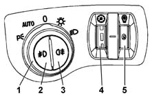
- Lights control knob
- Front fog lights control button
- Rear fog lamps control button
- Interior lights dimmer
- Dusk sensor exterior lights setting adjustment
The dusk sensor consists of two sensors: one global, capable of assessing the brightness upwards and one directional sensor, capable of assessing the brightness in the direction the vehicle is travelling in, in order to detect tunnels and driveways.
The sensor setting can be adjusted using the dimmer (4); the greater the sensitivity, the less outside light required to switch on the exterior lights.
When the knob (1) is turned to the AUTO position (lights switched on automatically), if the dusk sensor is not working properly, the side lights and the dipped headlamps will be switched on irrespective of the brightness outside and the instrument panel display will signal the failure of the sensor. The failure warning will remain activated as long as the knob (1) is in the AUTO position.
Rain Sensor
The rain sensor is designed to detect the present of rain on the windscreen and send a signal to the windscreen wiper electronic control unit which automatically adjusts the frequency of the blade strokes, during intermittent operation, according to the intensity of the rain.
The sensor is an electronic device which contains infrared light emitter diodes (LEDs) and an infrared light receiver; the device detects the presence and intensity of the rain according to the variation in the reflection between the light emitted and the light received that occurs during the change from a dry windscreen to a wet windscreen.
The rain sensor is automatically activated by placing the steering column switch unit right lever in position 1 (Fig. 13) and the adjustment range varies gradually from windscreen wiper off (no strokes) when the screen is dry to windscreen wiper second continuous speed (continuous fast operation) when the rain is heavy.
Fig. 13 - Rain sensor activation
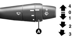
Each time the right lever is placed in position 1 to activate the rain sensor, the windscreen wiper carries out a stroke to confirm that the sensor has been switched on.
By turning the ring nut A (Fig. 14) it is possible to increase the sensitivity of the rain sensor, producing a faster variation from the windscreen wiper in the off position (no stroke) when the screen is dry to the second continuous speed position (continuous fast operation).
Fig. 14 - Rain sensor sensitivity adjustment
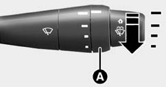
Key
__- minimum sensitivity
-- medium sensitivity
--- high sensitivity
---- maximum sensitivity.
If the sensitivity is altered whilst the rain sensor is working, increasing it, then the windscreen wiper carries out a stroke to confirm this change. When the rain sensor is switched on, if there is a malfunction, the intermittent operation of the windscreen wiper is activated, with the adjustment of the sensitivity set by the user, irrespective of whether or not there is rain on the screen.
VARIABLE GEOMETRY bi-xenon FRONT LIGHT CLUSTERS
The vehicle is equipped with front light clusters that combine the following functions:
- xenon dipped/main beam headlamps;
- main beam headlamps;
- side lights;
- direction indicators.
The type of bi-xenon lighting used, for both the dipped and main beam headlamps, has one bulb containing xenon gas.
In order to emit light an electric arc has to been produced and maintained between the two electrodes.
These light clusters feature:
- more effective lighting;
- increased range and regulation of the light beam;
- lower consumption at operating temperature;
- longer lasting bulb.
Each headlamp is equipped with an electronic control unit for checking the supply voltage. Precisely on account of their extreme brightness, these lights require a dynamic alignment control system.
This system is based on a control unit and two direction sensors, one fitted on the right side of the front suspension and the other on the left side of the rear suspension.
The electronic control unit operates on two levels:
- constantly realigning the orientation of the headlamps depending on the load of the vehicle;
- dynamically maintaining the alignment to compensate for vehicle pitching whilst driving.
There are 2 important advantages conferred by the automatic dynamic headlamp alignment control system:
- avoiding glare from oncoming vehicles;
- stabilizing the area illuminated for improved active safety.
LED REAR LIGHT CLUSTERS
The Lancia Thesis features a new solution for the rear light clusters consisting of the adoption of a series of LEDs instead of traditional incandescent bulbs.
In this way the driver no longer has to worry about the maintenance of the light clusters because the average life of LEDs (around 50,000 hours) means that lights have been developed where the light sources do not need replacing.
In addition, the low consumption of LEDs means a saving of around 60% compared with standard bulbs.
With the lights switched off, the housings appear completely monochromatic: the colour for the functions is produced directly by the light emitted by the LEDs. The vertical chrome coloured grooves in the lens and the metal border of the outer lens cover give the light cluster a 'chrome' appearance.
Photometric performance and standardization is achieved through two levels of high efficiency internal lenses.
FOLLOW ME HOME
This is a function of the lighting system that is designed to light up the area surrounding the vehicle for a certain period after the ignition has been switched OFF or the key extracted.
This function is activated by pulling the steering column switch unit lever towards the steering wheel, like the headlamp flasher function, within 2 minutes of switching off the engine. Each time the lever is activated the lights stay on 30 seconds up to a maximum of 210 seconds corresponding to the lever being activated 7 times after which they go out automatically.
The total time set (in seconds) is shown on the instrument panel display for around 20 seconds.
The Follow me home function can be interrupted by operating the lever and keepingi t pulled towards the steering wheel for more than 2 seconds.
CRUISE CONTROL
The cruise control function allows the vehicle to be driven at the desired speed (as long as it is above 30 km/h) without pressing the accelerator pedal as the speed is maintained automatically.
This reduces driver fatigue on motorways, particularly on long trips, because the set speed is maintained automatically.
The Cruise Control system controls (Fig. 15) are located on the specific steering column switch unit lever illustrated below.
Fig. 15 - Cruise Control controls
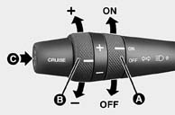
Key
A - ON/OFF ring nut/switch
B - Speed adjustment ring nut
C - RCL button (to restore the speed memorized)
There are two positions for switch A:
- OFF - the device is deactivated in this position
- ON - this is the normal device operating position.
When the device is switched on, the special symbol together with the message 'CRUISE CONTROL ON appear in the multifunction display.
Ring nut B is designed to memorize and maintain the vehicle speed or to increase or descrease the speed memorized:
- Turn ring nut B to the (+) position to memorize the speed reached or to increase the speed memorized.
- Turn ring nut B to the (-) position to decrease the speed memorized.
Each time ring nut B is operated, the speed is increased or decreased by around 1 km/h. Keeping the ring nut turned varies the speed stored constantly, the new speed reached is automatically maintained.
Button C (RCL) allows the speed memorized to be recalled after the device has been switched off automatically.
RADAR CRUISE CONTROL
The Radar Cruise Control (available on request for certain versions/markets) until now only available on versions with automatic transmission, is a device capable of asisting the driver by controlling both the cruising speed set and the distance from the vehicle in front.
After having selected the desired speed (similar to the Cruise Control system), the device maintains it also maintaining a safe distance from the vehicle in front;
The system intervenes on the accelerator, braking system and, on versions with automatic transmission only, on the gear change as well, depending on the data it receives from a radar sensor located under the front bumper.
The Radar Cruise Control is controlled both by the accelerator to increase the speed and by the brake to switch the system off and also by the following three controls (Fig. 16):
- button 1 RCL for recalling the speed memorized;
- ring nut 2 for increasing/decreasing the speed set;
- ring nut 3 for activating/deactivating the system and for setting the distance from the vehicle in front, depending on the speed
Fig. 16 - Radar Cruise Control system controls
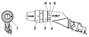
Key
- RCL button to restore the speed memorized
- Speed adjustment ring nut
- Radar Cruise Control/Settings on ring nut
- Radar Cruise Control OFF position
- 'Long distance' position
- 'Medium distance' position
- 'Short distance' position
The system is activated by the driver turning the ring nut to any position (b, c, d in Fig. 16). If the ignition key is turned to the OFF position or the Cruise Control on ring nut is in the OFF position, the speed memorized in cancelled and the system switches off.
The ring nut on the steering column switch unit (3 - Fig. 16) can be used to activate and set the distance to be maintained between the vehicle and the one in front depending on the speed.
For convenience the distance is expressed in seconds and represents the time required to cover the distance that separates the vehicle from the one in front. there are three different distance settings:
- 'long distance' corresponding to around 2 seconds;
- 'medium distance' corresponding to around 1.5 seconds;
- 'short distance' corresponding to around 1 second.
When the outside temperature goes below 3°C (measured by the outside temperature sensor) the system automatically sets the 'long distance' irrespective of the selection made by the user; when the temperature goes above 5°C the system can be reconfigured by the user.
Radar Cruise Control general warnings
The Radar Cruise Control system is not an 'automatic pilot' but a system that helps the driver.
Radar Cruise Control is not an anti-crash system: it is not capable of detecting and signalling obstacles in the driving path nor of stopping the vehicle if obstacles are present.
Any intervention by the driver on the brake or accelerator overrides the speed control system.
The system does not implement emergency braking: the maximum deceleration that can automatically be implemented by the system is limited in relation to the actual capacity of the vehicle's braking system and therefore only the driver is capable of carrying out emergency braking.
The system can only be switched on when the speed of the vehicle is between 30 and 160 km/h and is switched off automatically when the brake pedal is pressed. If the speed goes below 30 km/h when the system is switched on, a buzzer warns the driver until they regain control of the vehicle's speed.
KEYLESS SYSTEM
The Keyless System (available on request for certain versions/markets) is a passenger compartment access and engine starting system that allows the driver to enter their vehicle and start up the engine without using the key, simply by carrying a CID (Customer Identification Device) (Fig. 17) which contains a secret code. This system allows anyone with the CID to enter/leave the vehicle and open the boot.
The key and the remote control do not have to be used to unlock the doors: they are automatically unlocked the moment one of the exterior handles is pulled if authorized through recognition between the CID and the vehicle.
If the customer carries the CID in their pocket and approaches the locked vehicle, they simply have to pull the handle and the system automatically recognizes them, unlocks the doors and switches the alarm off.
When the clutch pedal or the brake pedal (for versions with automatic transmission) is pressed and the ignition knob is turned to the ON position, the steering is released: the instrument panel and the electric serivces are activated and the engine started up.
To switch off the engine, simply turn the knob from the ON position to the OFF position. When moving away from the vehicle, the system locks the vehicle automatically: the entire cycle takes place without needing to use a conventional key.
If the clutch pedal or the brake pedal (for versions with automatic transmission) is not pressed, the knob cannot be turned to the ON/STARTING position.
To ensure safety, identification only takes place if the owner is about 1 metre away from the door.
The CID (Fig. 17) contains:
- a transponder with the immobilizer codes programmed, the same as for the second generation Code system keys;
- a battery to supply the remote control transmitter for the alarm/central locking system;
- three locking, unlocking and boot opening buttons;
- an emergency mechanical key if the system is not working and for activating/deactivating the passenger air bag module. This key cannot be used to start the car.
The emergency mechanical key operates:
- the front door locks;
- the boot lock;
- the switch for deactivating the passenger air bag;
- the switch for deactivating the rear side air bags.
Fig. 17 - Views of the CID (Customer Identification Device) and its composition
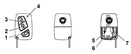
Key
- Boot release button
- Door lock button
- Door release button
- LED
- Printed circuit
- Emergency mechanical key
- Battery
The operation of the CID depends on various factors, such as possible interference with electro-magnetic waves emitted by external sources, the battery charge and the presence of metal objects near the CID and the vehicle.
The manoeuvres can always be carried out using the emergency key inserted in the CID.
If the CID battery is almost run down, a special symbol together with a a message warning the driver of the need to replace the battery as soon as possible will appear on the display in the instrument panel.
It should be remembered that the person using the CID should observe the following precautions so that all the system functions are working properly:
- To unlock the boot lid, the CID should be outside the vehicle within 1 metre of the boot.
- To activate the ignition switch functions, the CID should be inside the vehicle.
- If the CID is far away from the vehicle (e.g. because it is in a bag or jacket pocket) the doors cannot be unlocked or the vehicle started.
- To prevent the CID being inadvertently locked inside the vehicle, the boot lid does not close if the device is inside the luggage compartment or on the rear parcel shelf.
- If the vehicle is locked using the remote control whilst the CID is inside the passenger compartment, the doors will be locked without any exterior signalling.
Garage position (emergency operation)
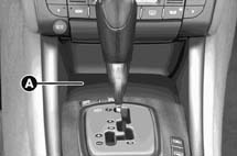
The housing for the CID during emergency operation or workshop servicing operations is located in the oddments compartment in the centre of the dashboard (A - Fig. 18) in front of the gear lever.
The Lancia CODE aerial, which sends the CID a radiofrequency signal which is then modulated and retransmitted to the actual aerial, is located near this compartment.
Fig. 18 - CID housing (garage position)
The modulated signal consists of the 'order word' with which the Lancia CODE control unit recognizes the CID and only then allows the knob to be turned and the engine started.
The CID can remain in this position indefinitely.
The electronic component housed in the CID is the 'passive' type which does not require its own electric supply and is therefore capable of operating even if the CID battery is run down.
The garage position (A - Fig. 18) should be used if the Keyless System is not working properly.
Under these circumstances it is possible to enter the vehicle by operating the front door lock only with the emergency key in the CID (the other doors remain locked), rest the CID in the garage housing, press the clutch pedal (manual gearbox) or the brake pedal (automatic transmission) and then turn the knob to start up the engine.
If turned on, the alarm system will be activated when the door is opened and the siren will start to sound but it will be deactivated when the starter knob is turned to the ON position.
The Autoclose function (automatic engagement of the central locking) is automatically activated the moment one leaves the vehicle taking the CID with them;
the alarm system will not be turned on in this case.
Whilst driving, the engine continues running even if the CID has been removed from the garage position.
The CID should be returned to the garage position for starting next time.
In emergency situations it is therefore advisable to leave the CID in the garage position until the operation of the system has been restored.
Only remove the CID from the vehicle when it must be left unattended.
ENGINE STARTING KNOB
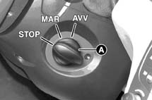
In place of the ignition switch and key, the vehicle is equipped with a switch operated by a knob A (Fig. 19) that allows the switch OFF, ON and STARTING functions to be activated.
Fig. 19 - Engine starting knob
The rotation of the knob is enabled by the CID in the vehicle and by pressing the clutch pedal (or the brake pedal on vehicles with automatic transmission0.
OFF Position
This position of the switch knob corresponds to: engine off and steering lock engaged. Certain electrical devices (e.g. the CONNECT) can work.
ON Position(MAR)
This on position corresponds to: instrument panel activated and steering lock released. All the electrical devices can work.
Starting Position (AVV)
This is the position for starting the engine: release the knob as soon as the engine starts up. The engine can only be started if the CID is in the passenger compartment.
Warnings for the operation of the engine starting knob:
- If the driver leaves the vehicle, taking the CID with them, after turning the knob to the ON position, the electrical devices switched on remain activated and the steering is released. The engine cannot be started up until the CID is returned to the vehicle. If the CID is not in the passenger compartment during starting, the instrument panel (if the knob is in the ON position) signals the impossibility of starting up the engine through the electronic key not recognized message. The engine cannot be started if the CID is in the luggage compartment. If the knob is in the ON position or the engine is running and the system no longer detects the presence of the CID on board (e.g. because one of the passengers has removed it or the driver has gone and left someone else in charge of the vehicle), the 'Battery/key' symbol appears in the instrument panel accompanied by the electronic key no longer in the vehicle and vehicle cannot be restarted message warning the driver not to switch off the engine and to get the CID.
Stopping the engine
To switch off the engine, turn the knob from the ON position to the OFF position: the engine will stop and the message that the steering will lock when the doors are locked will appear on the instrument panel.
Locking the steering
The steering lock is engaged automatically when the doors are locked using the remote control if the system has detected the simultaneous presence of the following conditions:
- engine switched off (knob in OFF position);
- clutch pedal released (brake pedal for versions with automatic transmission).
If the door locks are operated manually using the emergency key (in the CID) or automatically (with the CID far away from the vehicle), the steering lock is not engaged.
If the user has to leave the vehicle in an automatic car wash tunnel, they must remember to switch off the automatic electric parking brake (EPB) and leave the CID in the passenger compartment.
Releasing the steering
The steering lock is automatically released and the instrument panel and the electrical services activated when the system detects the simultaneous presence of the following conditions:
- presence of the CID in the vehicle;
- clutch pedal pressed (brake pedal for versions with automatic transmission).
It is vital to remember that, if the vehicle battery is run down, the steering lock cannot be released and the vehicle started. In this case, an auxiliary battery has to be connected to release the steering lock and start up the engine.
RECOGNITION SYSTEM SETTINGS
Some of the Keyless System recognition system functions can be personalized through the settings that can be selected on the CONNECT display.
The 'central unlocking' and 'driver's door unlocking' functions for the central locking can also be set for the Keyless System and operate as follows:
- central unlocking: all the vehicle doors are unlocked at the same time and access is allowed through any door;
- driver's door unlocking: access takes place through the driver's door whlst all the other doors remain locked preventing access to non authorized third parties; in this case the LED in the driver's door panel lights up in green whilst those for the other doors remain off.
The other recognition system settings that can be enabled/disabled are:
- automatic locking of the doors and boot;
- exclusion of the steering lock.
DOOR HANDLES AND LOCKS
For vehicles not fitted with the Keyless System, the doors can be opened and/or closed from the outside by pressing the buttons (A and/or B - Fig. 20) in the key grip (to unlock or lock the locks, respective) or by inserting the key in one of the front door locks and turning it. Pull the handle to open the door.
Fig. 20 - Key with remote control
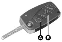
When the doors are unlocked using the remote control, the alarm system and the dead lock are also switched off.
The dead lock provides further protection against theft and makes it possible to mechanically disconnect the interior door opening handles so that the doors cannot be opened from the inside using the handles (e.g. after a window has been broken).
The electronic alarm is not switched off if the door is unlocked by turning the key in the lock.
The vehicle is fitted with electrified locks that move the mechanical parts during the manoeuvre of opening the doors.
There is a button (A - Fig. 21) inside each handle that activates the door opening servo control the moment the handle is tampered with.
Fig. 21 - Front door exterior opening handle
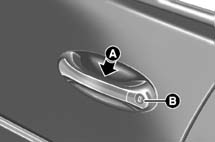
In emergencies (battery run down or electrical system faulty), press the button (B - Fig. 21) to open the doors with the locks released.
There is a two tone (red/green) LED (A- Fig. 22) in all the door panels that can be seen from the outside which signals the result of the door lock locking/unlocking operations.
Fig. 22
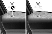
The LEDs come on for around 3 seconds in red after the locks have been locked and in green after unlocking. The LED signalling in the doors last for around 3 seconds and therefore in normal conditions they are switched off.
EASY ENTRY/EXIT SYSTEM
This system is only fitted on vehicles with electrically adjustable seats (available on request for certain versions/markets).
The Easy Entry/Exit system allows the driver to get in and out of the vehicle more easily. On vehicles equipped with this system, before the driver gets out of the vehicle, the steering wheel moves towards the dashboard and lifts up whilst the seat moves backwards.
The function is activated when the door is opened, even if the ignition key is in the OFF position or extracted.
When the door is opened to get into the vehicle, the driver finds that the seat and the steering wheel have already moved out of the way.
After sitting down and closing the door, when the ignition key is turned to the ON position, the seat and the steering wheel return to the normal driving position.
In addition to the above desciption, at the same time the door mirrors change position depending on the settings stored previously.
SUN ROOF
An electrically operated sun roof (Fig. 23), that can also be operated using a remote control, is fitted on the Lancia Thesis (available on request for certain versions/markets).
The sun-roof is adjustable by means of a selector to nine positions in addition to the closed position. This allows the air flow around the passenger compartment to be optimised.
To ensure safety during movement, the sun-roof is fitted with an anticrush safety device that cuts out movement in the presence of obstacles.
The system consists of:
- an electric displacement motor with Hall-effect position and speed sensors
- a sliding frame with a flexible rack pulling system;
- an electronic control unit built into the electric motor assembly;
- a selector with inhibition control, used to move the sun-roof to different positions.
- solar cells incorporated in the roof panel to supply the air conditioning system fan and therefore reduct the temperature in the passenger compartment (with the vehicle stationary and exposed to the sun).
Operation
The sun-roof is moved along the slide guides on the frame by means of an electric motor. This may be controlled manually by a selector or remotely by means of a command sent by the Body Computer to the control unit.
The motor moves flexible pulling racks housed in seats on the frame. These are anchored to extending mechanisms that suport the sun-roof, which is moved to the required point or position.
Fig. 23 - Sun roof
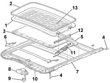
- Thermal tinted glass (Roof panel)
- Seal
- Blind
- Drainage pipe
- Drainage channel
- Deflector
- Mechanism guide
- Motor
- Selector
- Flexible racks
- Support mechanism
- Mechanism guard
- Solar cells
The sun roof has a blind underneath that slides together with the glass panel.
The sun-roof may be moved manually by means of the selector under the following conditions:
- with the ignition in the ON position (Key on);
- with the key in the OFF or PARK position (Key off) with the doors closed or with one front door open if one acts within two minutes the roof is enabled; the sun roof is diabled after this period has elapsed.
The operation of the sun roof, if open, is managed by the remote control in the Body Computer and is activated through signals coming from:
- remote control;
- key pawl in the door.
The sun roof should automatically move from open to closed within 15 seconds; irrespective of the position of the selector during this stage, the movement of the roof can be stopped manually within 10 seconds by pressing the selector vertically or rotating its position. The roof ignores the remote control and assumes the new position.
During movement, slide/tilt operations (including operations controlled remotely), the anticrush protection is always active
Do not disconnect the battery or the sun roof power supply whilst it is moving or within 5 seconds after the roof has stopped moving. If this happens, the control unit loses its memory and must be reset as described in the relevant paragraph.
Selector
All the sun roof functions (opening, closing and rear tilt) are controlled by the selector (A - Fig. 24). There are 6 positions (from S1 to S6) for sliding opening and 3 positions (from B1 to B3) for tilt opening (spoiler).
Position 0 corresponds to the roof closed; this position can be identified because it is stiffer to click into;
Pressing the selector activates an 'inhibiter' function (all the selector connections are earthed); this function is used to rest the control unit memory (see paragraph below)
Fig. 24 - View of manual control selector
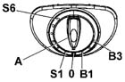
A - Selector
0 - Roof closed position
B1 - Minimum tilt position
B3 - Maximum tilt position
S1 - Minimum slide position
S6 - Maximum slide position
Control unit
Sun-roof movement is controlled by an electronic control unit housed in the casing integral with the motor. The unit processes signals from the selector or remote control via the body computer and also controls the anticrush protection function.
The function is controlled by the control unit, which receives position and speed information from Hall effect sensors fitted to the motor. When effort in excess of a certain threshold is detected, corresponding to a higher current uptake, this is interpreted as an obstacle. The control unit then stops the roof immediately and moves it back in the opposite direction by about 10 cm.
The control unit also receives a vehicle speed signal because the vacuum created at certain speeds could change the effort required to close the roof and under certain conditions this could be interpreted as an impediment. The control unit therefore uses this signal to ensure movement is not halted inadvertantly.
Resetting the control unit memory
The sun-roof could lose its movement memory if there is a break in the power supply (for example if the battery is disconnected/run down or a fuse is broken) whilst the roof is moving.
To rest the memory and initialize the safety system once again, carry out the following procedure:
- turn the selector (A - Fig. 24) to the end of travel position in an anti-clockwise direction, in the maximum tilt position (B3);
- press the selector (A) and keep it pressed until the roof reaches the maximum tilt position, moving in stages;
- release the selector after the roof has been still for at least 2 seconds;
- press the selector (A) again within 5 seconds and keep it pressed;
- within a further 5 seconds the roof will start to move carrying out a complete opening and closing cycle stopping in the roof closed position;
- release the selector after the roof has stopped for at least 2 seconds and then return it to the roof closed position (0).
The control unit memory has been reset. If the operation is interrupted before it is completed, repeat the procedure from the beginning.
ROOF PANEL (with solar cells)
The glass roof panel 1 (Fig. 25) incorporates a battery with 21 monocrystalline solar cells capable of providing a power output of 24 W.
The electrical energy produced by these cells (with the vehicle stationary, the ignition OFF and the sun roof closed or in the spoiler position) supplies the air conditioning system fan. The advantages of this solution are:
- a reduction in the high temperatures inside the passenger compartment produced by the rays of the sun;
- support for the air conditioning system, reducing its work load.
Fig. 25 - Roof with solar cells
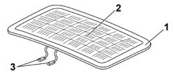
- Panel
- Solar cells
- Contacts
PARKING SENSORS
The parking sensors provide the driver with information relating to distance when approaching obstacles either in front of or behind the vehicle.
The information that there is an obstacle and its distance is transmitted to the driver by means of acoustic signals whose frequency depends on the distance from the obstacle.
By combining the direct visual information with the acoustic information produced by the system, the driver can therefore avoid any collisions.
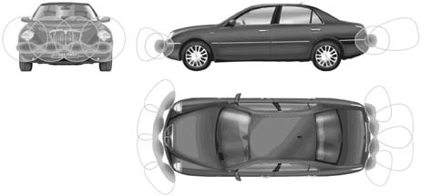
The system uses 4 sensors housed in the front bumper and 4 sensors housed in the rear bumper to measure the distance of obstacles.
It should be remembered that it is vital for the sensors in the bumpers to be kept clean and free from mud, dirt, snow or ice in order for the parking assistance system to work properly.
Sensor operating range
The sensors allow the system to control the front and rear of the vehicle.
Their position covers the middle and side areas of the front and rear of the vehicle.
If an obstacle is located in the middle area, it is detected at a distance of less than 1 m (front) or 1.50 m (rear).
Fig. 26
INSTRUMENT PANEL
There are two types of instrument panel for the Lancia Thesis: one for petrol versions and one for diesel versions.
The multifunction display in the instrument panel can show the following information:
Information on the standard screen
- Time
- Outside temperature
Vehicle status information
- Service interval
- Engine oil level (JTD versions only)
- Light dimmer position
- Failure message display
- Warning message display with symbols (danger ice warning, ASR off, etc.)
CONNECT information
(Information managed by the CONNECT and shown on the instrument panel display)
- Audio function information (radio station frequency)
- Navigation function information (pictograms)
- Telephone function information
- Voice box information
- SMS message receipt warning
Auxiliary driving systems information
- Cruise Control information
- Radar Cruise Control information
F.L.Ore.N.C.E. SYSTEM
The F.L.Ore.N.C.E (Fiat Luxury-car OrientEd Networks and Control Electronics) system, designed for the optimum management of the electrical and electronic functions on top of the range vehicles, is fitted on the Lancia Thesis.
The system consists of:
- three CAN communication networks that connect nodes belonging to three different areas (dynamic control of the vehicle and bodywork functions);
- a certain number of complementary serial lines used for fault diagnosis and other specific functions.
To allow the exchange of information, the electrical/electronic systems in the F.L.Ore.N.C.E. system, communicate through three physically separate networks known as the low speed B-CAN, high speed C-CAn and I-CAN. The latter is designed exclusively for the exchange of information between the TV tuner node and the CONNECT.
A double copper wire is the physical means used in CANs for automotive applications where one wire is associated to the higher level.
To transfer and receive information, all the electrical/electronic units are connted to the network by means of switching interfaces, integrated in the actual electronic units, known as transceivers.
Data to be shared between the B-CAN and the C-CAN is managed by the Body Computerwhich acts as a system gateway because it is equipped with both interfaces.
In practice, the Body Computer transfers information from the B-CAN (low speed) to the C-CAN (high speed) through the gateway and viceversa. Transfer may take place in two ways:
- directly, i.e. the entire message is copied exactly as it is onto the other network.
- indirectly: in this type of data transfer, the gateway composes a message for the destination network starting from different source messages. One or more messages received from the source network are dismantled, therefore the various signals contained in it are reassembled into a new message, sent later on to the destination network.
The gateway operation is only activated when the ignition is switched ON.
B-CAN specifications
The B-CAN manages the standard bodywork functions. This (low speed) network may feature up to 16 nodes (one per each control unit), all connected via a wire pair (BUS CAN), allowing a transmission speed of 50 kbit/sec to be reached.
The electronic units illustrated in Fig. 27 are connected to the Body Computer at the B-CAN.
Fig. 27 - B-CAN specifications
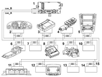
- Body Computer (NBC)
- Instrument panel node (NQS)
- Climate control node (NCL)
- Driver's door node (NPG)
- Info telematic node (NIT)
- Passenger door node (NPP)
- Driver geometry node (NAG)
- Passive entry node (NPE)
- Steering lock node (NBS)
- Passenger geometry node (NAP)
- Parking sensors node (NSP)
- Roof node (NIM)
- Steering wheel node (NVO)
- Luggage compartment node (NVB)
- Termination resistances (incoroporated)
The network interface (the transceiver) detects the overall and local faults and prevents data from being lost through the recovery function in accordance with the following list of faults that may occur in the B-CAN:
- CAN (B) wire or line interrupted.
- CAN (A) wire or line interrupted.
- CAN (B) wire or line short circuited at the battery (+).
- CAN (A) wire or line short circuited to earth (-).
- CAN (B) wire or line short circuited to earth (-).
- CAN (A) wire or line short circuited at the battery (+).
- CAN (A) wire or line short circuited with the CAN (B) wire or line.
The network interface loses any possibility of communication if both lines (A and B) are interrupted or both lines (A and B) are short circuited to earth.
I-CAN connection
The I-CAN connect the Info Telematic Node to the TV Tuner Node, managing the television controls sent by the user via the Connect.
Serial line
The serial line is an electric line consisting of a copper wire designated for the consecutive transfer of data between different electronic units (nodes), continuously alternating high (H) and low (L) voltage levels, i.e. serially.
C-CAN specificatations (Fig. 28)
The C-CAN (high speed) may feature up to 10 nodes (one for each electronic control unit), all connectged by means of a pair of wires (BUS CAN) thanks to which a transmission speed of 500 kbit/sec. can be reached.
The BUS C-CAN cables are plaited or twisted; this makes it possible to increase immunity against electro-magnetic interference from outside.
The network interface cannot communicate at all if one of the following situations arises in the C-CAN:
- interruption of one of the two lines (H and L);
- short-circuit between the two lines (H and L);
- short-circuit of one line (H) (L) at the battery (+),
- short-circuit of one line (H) (L) to earth (-).
Figure 28 illustrates the electronic units connected to the Body Computer (NBC) via the C-CAN.
Fig. 28 - C-CAN
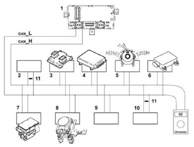
- Body Computer (NBC)
- Parking brake node (NPB)
- Engine control node (NCM)
- Automatic transmission node (NCA)
- Steering angle sensor node (NAS)
- Lateral yaw sensor node (NYL)
- Adaptive cruise control node (NAC)
- Braking system node (NFR)
- Gear selector lever node electronic unit (NSC)
- Brake assistant node electronic unit (NBA)
- Termination resistances at parking brake node (NPB) and at braking system control unit (NFR)
E.O.B.D. (Electronic On Board Diagnostic) Connector
All the diagnostic lines reach the EOBD connector in the Body Computer. This connector is responsible to the fault diagnosis of the nodes (control units) connected to the B-CAN low transmission speed, whilst the fault diagnosis of the control units connected to the C-CAN takes place via the special K line.
List of nodes and control units on the Lancia Thesis
Below is a diagram (Fig. 29) and a list summarizing the nodes and control units on the vehicle.
Fig. 29 - Nodes and control units
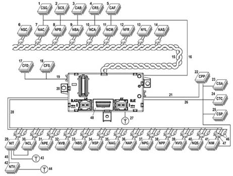
- Power steering control unit (CSG)
- Controlled suspension control unit (SCS)
- Air Bag control unit (CAB)
- Additional heater control unit (CRS)
- Headlamp alignment control unit (CAF)
- Gear selector lever node (NSC)
- Adaptive cruise control node (NAC)
- Parking brake node (NPB)
- Brake assistant node (NBA)
- Automatic transmission node (NCA)
- Engine control node (NCM)
- Braking system node (NFR)
- Lateral yaw sensor node (NYL)
- Steering angle node (NAS)
- C-CAN high speed twisted line
- Serial line K
- Right headlamp control unit (CFD)
- Left headlamp control unit (CFS)
- Two-way serial line
- Body Computer (NBC)
- Line K
- Tyre pressure control unit (CPP)
- Anti-theft alarm control unit (CSA)
- Windscreen wiper control unit (CTC)
- Rain/dusk sensor control unit
- A BUS line
- Lancia Code aerial
- B-CAN low transmission speed parallel line (twin)
- Info telematic node (NIT)
- Climate control node (NCL)
- Passive entry node (NPE)
- Luggage compartment node (NVB)
- Steering lock node (NBS)
- Parking sensors node (NSP)
- Driver geometry node (NAG)
- Passenger geometry node (NAP)
- Driver's door node (NPG)
- Passenger door node (NPP)
- Steering wheel node (NVO)
- Instrument panel node (NQS)
- Roof node (NIM)
- TV tuner node
- GPS - GSM aerial
- TV aerial
- I-CAN
- Termination resistances (incoroporated)
- Communication interface (transceiver) built into the node
- 16 pin EOBD (Electronic On Board Diagnostic) socket
CONNECT Nav +
The CONNECT Nav + also known as the N.I.T. (Info Telematic Node), consists of an electronic control unit located in the centre of the dashboard which incorporates the information, telematic, audio/video and climate control system programming functions.
The CONNECT Nav + is equipped with a front panel connected to the main electronic unit that includes a multifunction display and a series of buttons for activating the individual functions; it can be easily used by either the driver or the passenger and involves the following systems/services:
- radio, with cassette player and CD player/changer;
- colour TV tuner with voice commands;
- trip computer;
- check control display;
- GSM radio phone with voice recognition module;
- voice box
- navigator with voice controls.
- vehicle set-up (programming of door opening/closing, front seat position adjustment/memorizing, additional heating system programming, etc.).
- Targasys Services for Connect (emergency call, medical consultation, roadside assistance, road condition messages, etc.)
The Info Telematic Node (NIT) manages the following tasks:
- receives and sends information on the B-CAN line (e.g. diagnosis, warning lights, commands, data)
- incorporates the controls for interaction with the various menus
- manages a high definition colour display for the navigation system or the TV
- interconnects with the dashboard wiring for connection to the vehicle's electrical system
- interconnects with the telematic wiring for the TV tuner point / point connection, rear telecamera, videocassette player
- there is preparation for connection with components such as a DVD, rear multi video screens, etc.,
- it interfaces with the GPS, GSM and radio aerials through coaxial cables
The info telematic node features a thermal protection function that limits operation as the internal temperature increases to prevent permanent damage to the system.
The system works in full at internal temperatures below 85 °C.
Since the normal operation of the system produces an increase of around 20 °C, even through there is a cooling fan at the back of the NIT, as a result if the temperature in the passenger compartment is around 65 °C the system reaches its temperature limit and is deactivated
Front control panel
The front control panel can be separated from the NIT unit and is specifically identifiable as the electronics that also incorporates the CD and CASSETTE players and the housing for the telephone card.
The two components are connected by means of two connectors at the back of the panel. The devices in the CONNECT control panel are listed below and illustrated.
Fig. 30 - CONNECT Nav+ control panel
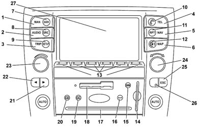
- MAIN screen selection button
- AUDIO functions activation button
- On board computer screen selection button (TRIP)
- TELEPHONE functions activation button
- NAVIGATION functions activation button
- Navigation map mode selection button
- DARK mode selection button, the display is completely obscured.
- Source selection button (FM1, FM2, FM3, AS, MW, LW, CC, CD, CDC, TV)
- Vehicle SET-UP function selection button
- Send/receive/end telephone call/SMS button
- Last navigation audio information repeat button
- Targasys services access button
- Multifunction button (the function will be shown on the display by the button)
- Housing for telephone SIM card
- SIM card eject button
- Turning over the cassette being listened to
- Housing for navigation CD ROM or audio CD ROM
- Housing for audio cassette
- Audio cassette eject button
- CD ROM eject button
- Multifunction 'forward' button (search/scan for higher radio frequency, select next cassette/CD track, fast forward cassette tape, select next TV channel)
- Multifunction 'backward' button (search/scan for lower radio frequency, select previous cassette/CD track, fast rewind cassette tape, select previous TV channel)
- Pressing: system switched on/off - Turning: volume adjustment
- Turning: selection of function - Pressing: confirming function selected
- Exit from selection list or move to a derived or higher menu.
- Infrared receiver for remote control / panel light photodiode
- Display
AUDIO SYSTEM
The audio reception and reproduction system for the vehicle has been developed taking the acoustic properties of the passenger compartment into account to offer optimum sound quality. The system, incorporated in the Connect, comes in two different versions: a basic version and a HI-FI (BOSE) version.
Basic version
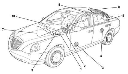
The basic version includes (Fig. 31):
- FM - AM (MW and LW) radio receiver with CD player and cassette player (1);
- radio controls on the steering wheel (2)
- speakers housed in the front door panels (3)
- speakers housed in the rear door panels (4)
- speakers housed in the shelf under the rearscreen (5)
- FM - AM aerial built into the rearscreen (6)
- coaxial cable connected to the aerial (7)
- aerial amplifier/interference suppressor (8)
- cable connected to the CD-Changer (optional) (9)
- CD-Changer (optional) (10)
- supply leads for connecting the radio and the speakers
Fig. 31 - Audio system
BOSE HI-FI Version
A BOSE hi-fi system is available on request with special speakers and an outside amplifier that guarantees high fidelity sound with crystal clear treble sounds and full, rich base sounds.
Unlike the basic system fitted as standard, the Bose HI-FI system is equipped with the following:
- two (168 mm diameter) woofer speakers and two (50 mm diameter) tweeter speakers coaxial and built into the woofers fitted in the front doors;
- two (160 mm diameter) high efficiency, broad band midrange speakers housed in the rear door panels;
- two (230 mm diameter) subwoofer speakers built into the shelf under the rearscreen;
- a speaker in the top part in the centre of the dashboard;
- a high powe HI-FI amplifier (total musical power 300 W) with an analogue equalizer housed on the right of the luggage compartment;
The other components (radio, aerial, etc.) are the same as those on the system fitted as standard.
TV TUNER
The vehicle may be equipped with a TV tuner that makes it possible to view video images on the Connect display and listen through the vehicle's audio system.
The TV tuner is operated by the NIT unit through the I-CAN connection. The video signal coming from the TV module is transmitted to the LCD in the form of an RGB/C Sync. signal only when the vehicle is stationary. for safety reasons, the video signal is automatically suppressed if the speed of the vehicle exceeds 7 km/h; the audio signal, on the other hand, is maintained even when the vehicle is driving at higher speeds.
Up to 5 broadcasters can be stored and the brightness, contrast and colour saturation can be adjusted. Depending on the location, the following televisual standards can be selected:
- Central European PAL
- Italian PAL
- UK PAL
- Eastern European SECAM
- French SECAM
CONTROLS ON THE STEERING WHEEL AND REMOTE CONTROL
The main controls for the Connect function and the VOICE button for activating voice commands are duplicated on the steering wheel.
The infrared remote control also controls some of the main audio and TV system functions. The diagram below (Fig. 32) illustrates the control buttons on the steering wheel and the remote control.
Fig. 32 - Controls on the steering wheel and remote control
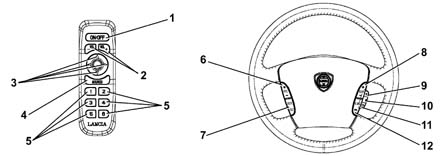
- Radio mode: volume cancellation/reactivation (Audio Mute). Cassette/CD mode: stop track listened to. TV mode: switch television on/off
- Increase/decrease volume
- Radio mode: search/scan for other broadcasters. Cassette/CD mode: select next/previous track and fast forward/rewind. TV mode: search for first channel that can be tuned into at a higher/lower frequency
- Audio source selection (Radio - cassette - CD - CD-Changer - TV)
- Radio mode: select station memorized (brief press), memorize station listened to (long press). CD-Changer mode: select CD. TV mode: select channel memorized
- Volume increase/decrease
- Audio source selection (Radio - cassette - CD - CD-Changer - TV) and activation of voice commands or message recording
- Radio mode: search for first broadcaster at a higher/lower frequency. Cassette/CD mode: select next/previous track. TV mode: search for first channel that can be tuned into at a higher/lower frequency
- Sliding upwards for functions shown on Connect display
- Confirmation of function selected
- Sliding downwards for functions shown on Connect display
- Selection of main screens (MAIN, AUDIO, TRIP, SETUP, TEL, NAV, CONNECT) and telephone button for receiving, sending, ending and refusing a call and reading SMS messages.
OPERATIONS IN NETWORK
- For the routine P.D.I. operations refer to the following subjects in Service News 3/2002: 00.04.02 (Various Models - list of operations) and 00.06.02 (specific operations for the Thesis).
- For general information, technical data, descriptions and operation, fault diagnosis, tests, repair procedures and wiring diagrams, refer to the Service Manual available on CD ROM which, starting from this model, has been improved to make it easier toconsult.
- For the fault diagnosis of electronic systems, use the Examiner updated with the release of programme 5.20 or later.
- If the following components are being replaced: the instrument panel, Body Computer and N.I.T.with ones supplied as spares, the component must be configured, using the Examiner following the PROXI alignment procedure.
- The programming of the CODE 2 function and any central locking and alarm remote controls should always be carried out using the Examiner selecting the Body Computer system if the vehicle is not equipped with the Keyless System; if the vehicle is equipped with the Keyless System, select 'Passive Entry DELPHI F.L.
- To order the following parts from the Parts Dept: Body Computer, lock barrel kits, keys, CIDs and CODE Cards, the same procedure for ordering CODE2/Alarm system components is valid, i.e. using a Personal Computer (DCS) for the Network which is on line or by Fax for users who are not connected.
Parts & tools for this job For 2002 Lancia Thesis
Links open Amazon search results in a new tab. As an Amazon Associate I earn from qualifying purchases.