
CAUTION: During the engine removal
- Make
- Land Rover
- Model
- Defender V8i Workshop Manual Supplement
- Section
- Repair › CAUTION: During the engine removal
EngineCAUTION: During the engine removal
- Position jack beneath gearbox fluid pan and
- With assistance, lower engine into engine
- With assistance, align engine to bell housing
- Fit bolts securing bell housing to engine and
- Remove jack supporting gearbox fluid pan.
- Lower engine hoist ensuring mountings are
- Disconnect lifting chains from engine eyes.
- Remove lifting tool
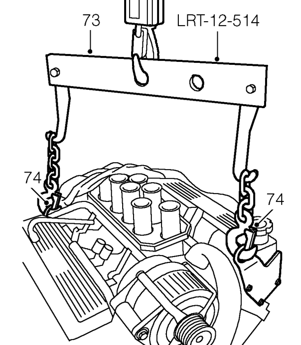
- Fit engine lifting tool LRT-12-514 to hoist. 94. Remove hoist from above vehicle.
- Lower hoist and connect lifting chains to engine 95. Position engine harness around engine. brackets. 96. Connect ignition coil multiplug and secure to
- Raise hoist until lifting chains become taught and use a jack to support gearbox. 97. Connect LH injector multiplugs.
- Remove 6 bell housing to engine bolts. 98. Connect gauge temperature thermistor.
- With assistance, raise engine on hoist from 99. Connect multiplug to fuel temperature sensor. engine compartment. 100. Connect multiplug to ECT sensor.
- Connect RH bank HT leads to spark plugs and
CAUTION: During the engine removal
procedure ensure that the engine does not 102. Connect RH rocker cover breather pipe to ram damage any surrounding components.
- Connect RH injector multiplugs.
- Move engine clear of vehicle and lower onto 104. Align engine harness to RH side of inlet manifold work bench.
- Disconnect lifting chains from engine. 105. Fit heater hose/pipe assembly to inlet manifold
- Raise hoist and position aside.
- Align heater pipe to bracket and secure with
Refit
- Position alternator terminal leads and secure.
- Clean engine and gearbox mating faces. 108. Route harness down front of engine.
- Clean dowel and dowel holes. 109. Connect Lucar to oil pressure switch.
- Position hoist above engine. 110. Connect multiplug to camshaft position sensor.
- Connect lifting chains to engine. 111. Connect radiator bottom hose to heater pipe and
- Raise engine from work bench and position above engine compartment. 112. Raise vehicle.
raise transmission to ease alignment of bell housing to engine.
CAUTION: Use a block of wood or hard rubber pad to protect fluid pan.
compartment.
- CAUTION: During the engine fitment
- procedure ensure that the engine does not
- damage any surrounding components.
dowels.
tighten to 46 Nm (34 lbf.ft).
NOTE: Align harness brackets to 2 uppermost bell housing retaining bolts.
aligned with chassis brackets.
LRT-12-514 from hoist.
bracket.
secure to guides.
housing.
and secure with screws.
and secure with clip.
screw.
secure with clip.
Parts & tools for this job For Land Rover Defender
- PARTEngine gasket setSearch: Land Rover Defender engine gasket set
- TOOLTorque wrenchSearch: 3/8 inch torque wrench
- TOOLFeeler gauge setSearch: feeler gauge set
Links open Amazon search results in a new tab. As an Amazon Associate I earn from qualifying purchases.