
Introduction
- Make
- Land Rover
- Model
- Discovery Electrical Troubleshooting Manual
- Year
- 1996
- Section
- Introduction i › Introduction
INTRODUCTION
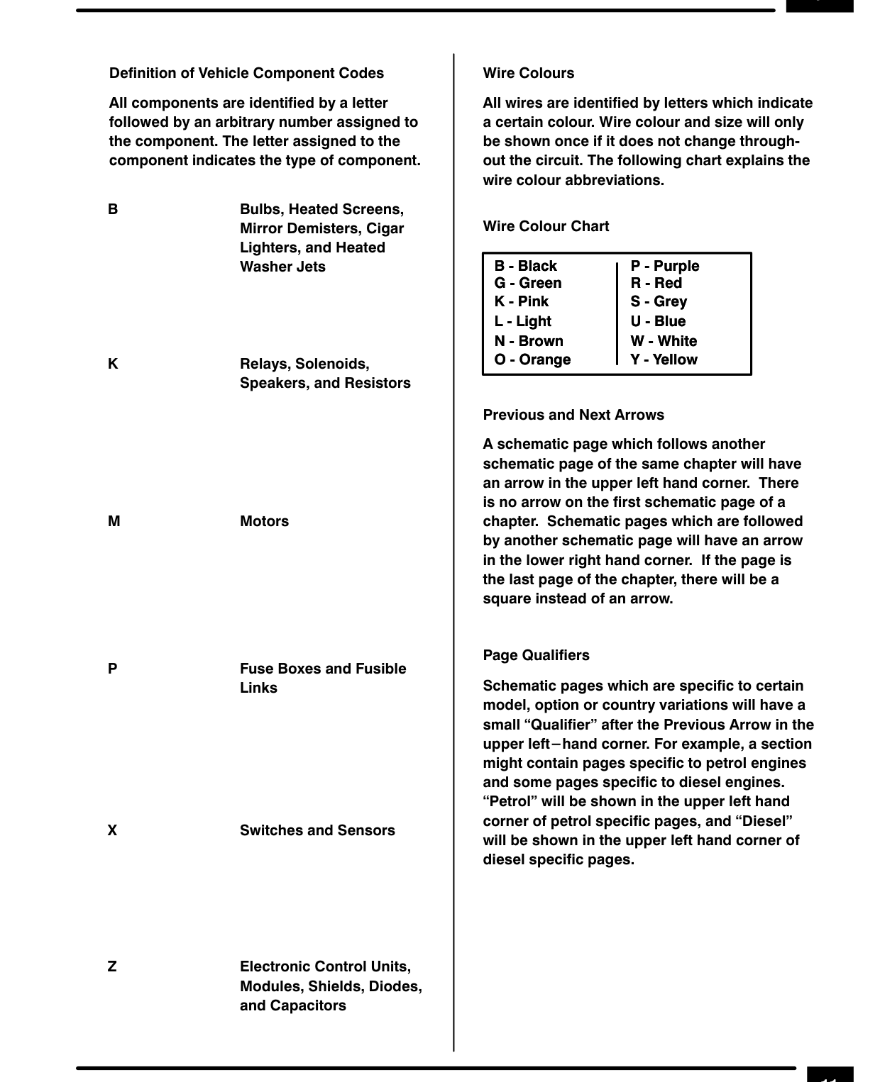
Definition of Vehicle Component Codes
All components are identified by a letter followed by an arbitrary number assigned to the component. The letter assigned to the component indicates the type of component.
Bulbs, Heated Screens, Mirror Demisters, Cigar Lighters, and Heated Washer Jets
Relays, Solenoids, Speakers, and Resistors
Motors
Fuse Boxes and Fusible Links
Switches and Sensors
Zz Electronic Control Units, Modules, Shields, Diodes, and Capacitors
Wire Colours
All wires are identified by letters which indicate a certain colour. Wire colour and size will only be shown once if it does not change throughout the circuit. The following chart explains the wire colour abbreviations.
Wire Colour Chart
B - Black P - Purple G - Green R - Red K - Pink S - Grey L - Light U - Blue N - Brown W - White O - Orange Y - Yellow
Previous and Next Arrows
A schematic page which follows another schematic page of the same chapter will have an arrow in the upper left hand corner. There is no arrow on the first schematic page of a chapter. Schematic pages which are followed by another schematic page will have an arrow in the lower right hand corner. If the page is the last page of the chapter, there will be a square instead of an arrow.
Page Qualifiers Schematic pages which are specific to certain model, option or country variations will have a small “Qualifier” after the Previous Arrow in the upper left—hand corner. For example, a section might contain pages specific to petrol engines and some pages specific to diesel engines. “Petrol” will be shown in the upper left hand corner of petrol specific pages, and “Diesel” will be shown in the upper left hand corner of diesel specific pages.
Parts & tools for this job For 1996 Land Rover Discovery
- TOOLTorque wrenchSearch: 3/8 inch torque wrench
- TOOLSocket setSearch: socket set metric
- BOOKHaynes manualSearch: Haynes manual Land Rover Discovery
Links open Amazon search results in a new tab. As an Amazon Associate I earn from qualifying purchases.