
Introduction
- Make
- Land Rover
- Model
- Discovery Electrical Troubleshooting Manual
- Year
- 1997 on
- Section
- I introduction › Introduction
INTRODUCTION
Self—powered Test Light and Ohmmeter Use a self—powered test light or onmmeter to check for continuity. The ohmmeter shows how much resistance there is between two points along a circuit. Low resistance means good continuity. CAUTION: Never use a self—powered test light on circuits that contain solid state devices. Damage to these devices may result.
Diodes and solid state devices in a circuit can make an ohmmeter give a false reading. To find out if a component is affecting a measurement, take one reading, reverse the leads, and take a second reading. If the readings differ, the component is affecting the measurement.
Circuits that contain solid state devices should only be tested with a 10 megohm or higher impedance digital multimeter.
A self—powered test light consists of a light bulb, battery and two leads. If the leads are touched together, the bulb will go on.
A self—powered test light is only used on an unpowered circuit. First, disconnect the battery or remove the fuse that feeds the circuit you are working on. Select two points along the circuit through which there should be continuity. Connect one lead of the self—powered test light to each point. If there is continuity, the test light’s circuit will be completed and the bulb will go on.
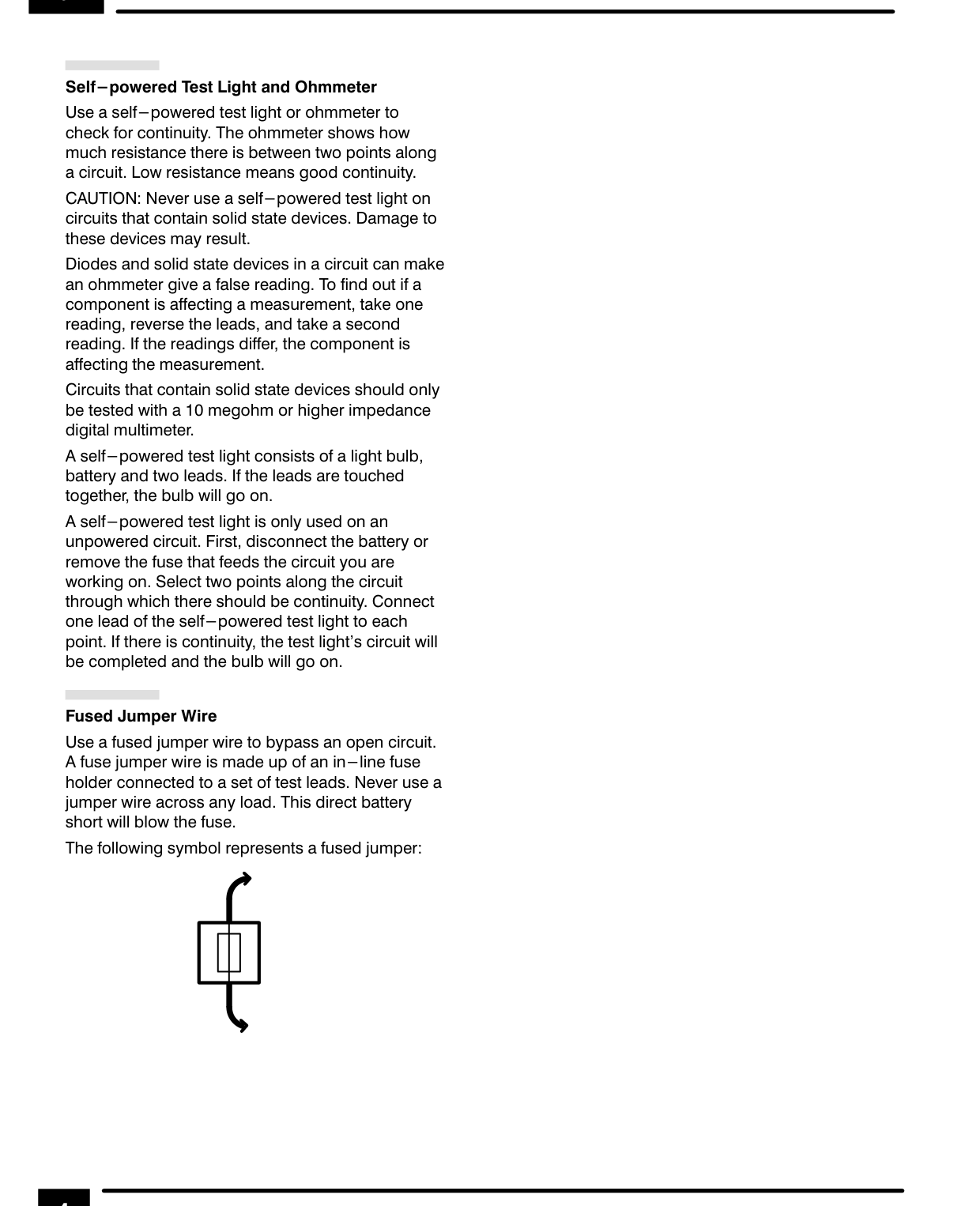
Fused Jumper Wire Use a fused jumper wire to bypass an open circuit. A fuse jumper wire is made up of an in—line fuse holder connected to a set of test leads. Never use a jumper wire across any load. This direct battery short will blow the fuse.
The following symbol represents a fused jumper:
Parts & tools for this job For 1997 Land Rover Discovery
- TOOLTorque wrenchSearch: 3/8 inch torque wrench
- TOOLSocket setSearch: socket set metric
- BOOKHaynes manualSearch: Haynes manual Land Rover Discovery
Links open Amazon search results in a new tab. As an Amazon Associate I earn from qualifying purchases.