
Brake pedal switch (Engine management system - EDC)
- Make
- Land Rover
- Model
- Freelander Workshop Manual
- Year
- 1998–2000
- Section
- Description and operation › Brake pedal switch
Throttle pedal movement causes voltage across the potentiometer to vary. The ECM calculates the rate of change of the voltage signal in positive (acceleration) or negative (deceleration) directions. From this, the ECM can determine the required engine speed, rate of acceleration or deceleration and apply acceleration enrichment, deceleration fuel metering, or over-run fuel cut-off.
The ECM calculates the ’maximum allowable fuel quantity’ from the input signal according to strategies such as smoke limitation and active surge damping to calculate the final figure. If the signal from the throttle potentiometer is smaller than the maximum allowable quantity, then the requested quantity will be injected. However, if the requested quantity is greater than the maximum allowable quantity, then the maximum allowable quantity will be injected rather than that demanded.
If the TP sensor fails, the malfunction indicator lamp on the instrument panel is illuminated. The ECM limits the engine speed to 1060 rpm and the air conditioning (if fitted) is inoperable.
Brake pedal switch

The brake pedal switch is mounted on the pedal box. The switch informs the ECM when the vehicle is braking and allows it to implement active surge damping and over-run fuel cut-off.
The ECM has one brake input which is monitored for plausibility with the TP sensor. If the brake pedal switch fails, there will be no effect on the engine management system.
Glow plug relay
The glow plug relay is located behind the battery tray, below the engine compartment fuse box.
When the starter switch is turned to position ’II’, the ECM energises the glow plug relay and illuminates the glow plug warning light on the instrument panel. The glow plug relay supplies a current from the battery to the four glow plugs to reduce post start emissions and assist cold starting by raising the temperature of the compressed air to ignition point.
Glow plugs
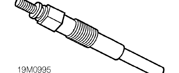
The four glow plugs are located in the forward face of the cylinder head below their respective injector. Each glow plug draws a current of 23 to 25 Amps. The current draw has a linear decline to 11 Amps as the glow plug warms.
Parts & tools for this job For 1998 Land Rover Freelander
- TOOLOBD2 scannerSearch: OBD2 scanner
- TOOLDigital multimeterSearch: automotive digital multimeter
- TOOLBack-probe test leadsSearch: back probe test leads
Links open Amazon search results in a new tab. As an Amazon Associate I earn from qualifying purchases.