
Fuel Injection Timing (Engine management system - EDC)
- Make
- Land Rover
- Model
- Freelander Workshop Manual
- Year
- 1998–2000
- Section
- Description and operation › Fuel Injection Timing
Fuel Injection Timing
The ECM determines the optimum fuel injection timing for the injection pump based on the signals it receives from the following sensors:
- Crankshaft Position (CKP) sensor - Engine speed and crankshaft position
- Needle lift sensor - Start of injection
- Engine Coolant Temperature (ECT) sensor - Engine temperature
- Manifold Absolute Pressure (MAP) sensor - Engine load
- Intake Air Temperature (IAT) sensor
Basic Fuel Injection Timing
Crankshaft Position (CKP) sensor
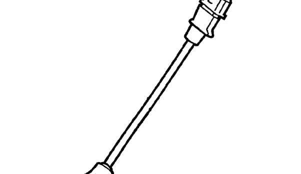
The speed and position of the engine is detected by the CKP sensor which is bolted to, and projects through, the gearbox adapter plate adjacent to the flywheel.
The CKP sensor is an inductive sensor containing a coil and a permanent magnet which provides a magnetic field. The sensor is situated such that an air gap exists between it and the flywheel. Air gap distance is critical for correct operation.
The flywheel has four poles positioned equally around the crankshaft circumference at 90 degree intervals. When the flywheel rotates and a pole passes the CKP sensor, it disturbs the magnetic field inducing a voltage pulse in the coil. This pulse is transmitted to the ECM.
Four pulses are transmitted to the ECM for each revolution of the flywheel. By calculating the number of pulses that occur within a given time, the ECM can determine the engine speed. The output from this sensor, when used in conjunction with that from the needle lift sensor, is used for idle stabilisation and reference for injection timing.
If the CKP sensor fails, the malfunction indicator lamp on the instrument panel is illuminated. The ECM enters a default mode and uses signals from the needle lift sensor to enable the ECM to continue functioning but with a reduction in engine performance and a higher than normal idle speed. Starting difficulties may also be experienced.
Parts & tools for this job For 1998 Land Rover Freelander
- PARTFuel filterSearch: Land Rover Freelander 1998 fuel filter
- TOOLFuel pressure test kitSearch: fuel pressure test kit
- TOOLFuel line disconnect toolSearch: fuel line disconnect tool
Links open Amazon search results in a new tab. As an Amazon Associate I earn from qualifying purchases.