
Vehicle Speed Sensor (VSS) (Engine management system - EDC)
- Make
- Land Rover
- Model
- Freelander Workshop Manual
- Year
- 1998–2000
- Section
- Description and operation › Vehicle Speed Sensor (VSS)
Vehicle Speed Sensor (VSS)
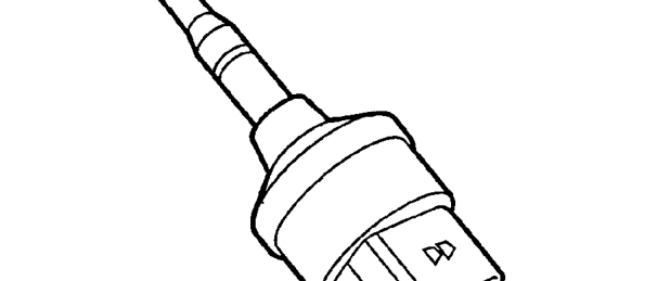
The VSS is located on the top face of the gearbox housing at the rear of the engine. The VSS is driven by a shaft from the final drive gear where it is converted into an electrical signal proportional to road speed.
The output from the VSS is used to drive the instrument panel speedometer in addition to providing a signal to the ECM. The ECM uses this signal, along with other inputs, to provide active surge damping, adjust idle stabilisation and the quantity of fuel being delivered to the injectors.
On vehicles fitted with ABS, the speed sensor is not fitted. A dummy sensor is fitted to blank the sensor port. The ECM and the speedometer receive their signals from the ABS ECU, which it calculates from each ABS wheel sensor.
If the VSS fails, the malfunction warning lamp on the instrument panel is illuminated. The ECM uses a substitute value of 1.8 mph (3 km/h), active surge damping is removed and the air conditioning (if fitted) is inoperable.
Throttle Position (TP) sensor
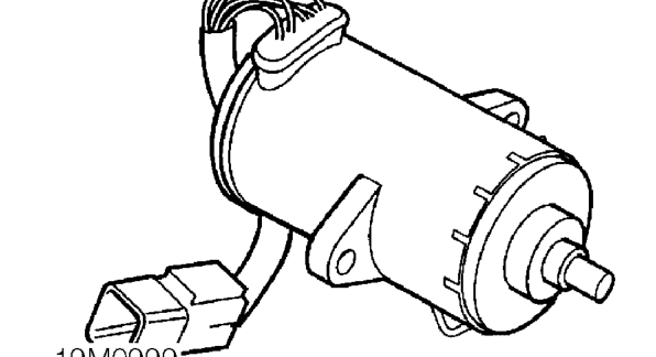
The TP sensor is mounted on the pedal box and is connected by a linkage to the throttle pedal. Movements of the throttle pedal are sensed by the TP sensor and a signal sent to the ECM.
The engine management system is a ’Drive by Wire’ system. The throttle pedal is not physically connected to the fuel injection pump by a mechanical linkage as in a traditional injection system, but instead the amount of fuel injected is controlled entirely by the ECM.
The TP sensor consists of a thick film potentiometer together with a sender switch. With the throttle pedal at rest the switch is open. The sender switch signal from the potentiometer is used by the ECM to implement idle speed control and over-run fuel shut-off. When the throttle pedal has been moved enough to rotate the potentiometer more than 9 degrees, the switch closes.
When the potentiometer is moved, the sender switch signals a logic input to the ECM. The ECM then checks the voltage signal from the potentiometer. This voltage is compared with a pre-programmed value to check the potentiometer is working correctly.
Parts & tools for this job For 1998 Land Rover Freelander
- TOOLOBD2 scannerSearch: OBD2 scanner
- TOOLDigital multimeterSearch: automotive digital multimeter
- TOOLBack-probe test leadsSearch: back probe test leads
Links open Amazon search results in a new tab. As an Amazon Associate I earn from qualifying purchases.