
Steering (Valve unit): Description and operation
- Make
- Land Rover
- Model
- Freelander Workshop Manual
- Year
- 1998–2000
- Section
- Description and operation › Valve unit
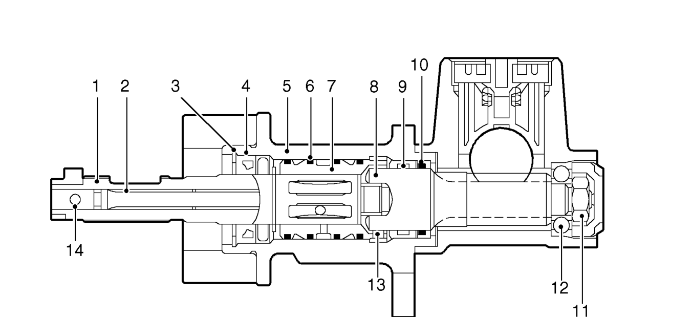
VALVE UNIT
- Input shaft
- Torsion bar
- Circlip
- Oil seal
- Valve housing
- PTFE ring - 4 off
- Outer sleeve
The torsion bar is fitted inside the rotor and is connected to the input shaft and the pinion shaft with pins. The central diameter of the torsion bar is machined to a smaller diameter than at each end. The smaller diameter allows the torsion bar to twist in response to torque applied from the steering wheel in relation to grip of the tyres on the road surface.
- Pinion shaft
- Bearing
- Oil seal
- Nut
- Bearing
- Pin - Pinion shaft to torsion bar
- Pin - Rotor to torsion bar
The pinion shaft has machined teeth on its central diameter which mate with the teeth on the steering rack. A bore in the upper end is machined with loose splines which mate with similar splines on the rotor. The pinion shaft locates in a cast housing which is part of the steering rack and rotates on ball and roller bearings.
Parts & tools for this job For 1998 Land Rover Freelander
- PARTEngine gasket setSearch: Land Rover Freelander 1998 engine gasket set
- TOOLTorque wrenchSearch: 3/8 inch torque wrench
- TOOLFeeler gauge setSearch: feeler gauge set
Links open Amazon search results in a new tab. As an Amazon Associate I earn from qualifying purchases.