
Workshop Manuals Factory service & repair Land Rover
01 Introduction02 Multiport fuel injection (MFI-V8)03 Diesel04 Starting and charging05 Cruise control06 Transfer gearbox07 Automatic gearbox08 Ignition and shift interlock09 Anti-lock brake system10 Data link connector11 Instruments12 Warnings and indicators13 Horns14 Radio15 Wash/wipe16 Heated front screen17 Heated rear screen18 Electrochromic rear view mirror19 Headlamps20 Side lamps21 Stop lamps22 Direction indicator lamps23 Reversing lamps24 Fog guard lamps25 Interior lamps26 Cigar lighter/clock27 Heating and ventilation (without A/C)28 Heating and ventilation (WITH A/C)29 Power windows30 Sunroof31 Power seats32 Power33 Memory seats34 Heated seats35 Memory mirrors36 Trailer auxiliary socket37 Air suspension38 Security/central locking39 Power distribution40 Fuse details41 Ground distribution42 Component location table43 Component location views44 Connector views45 Harness routing46 Index
Land Rover Range Rover P38 Electrical Troubleshooting Manual (1995)09 · Anti-lock brake system
09 · Brakes

Anti-lock brake system – circuit diagram

Make
Land Rover
Model
Range Rover P38 Electrical Troubleshooting Manual
Year
1995
Section
Circuit diagram › Anti-lock brake system – circuit diagram
Anti-lock brake systemAnti-lock brake system – circuit diagram

ANTI-LOCK BRAKE SYSTEM – CIRCUIT DIAGRAM
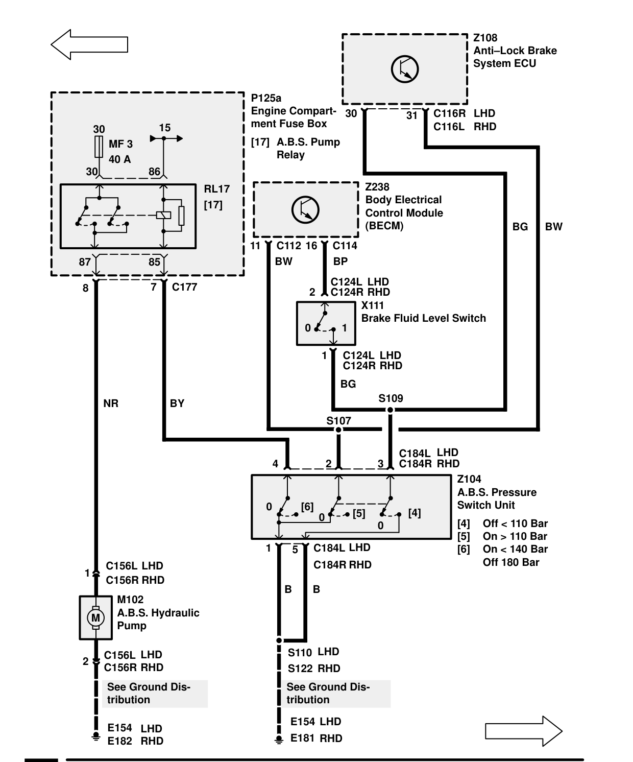
Anti-Lock Brake System – Circuit Diagram

Components on this page

  • M102 A.B.S. Hydraulic Pump
  • X111 Brake Fluid Level Switch
  • Z104 A.B.S. Pressure Switch Unit
  • Z108 Anti-Lock Brake System ECU
  • Z238 Body Electrical Control Module (BECM)

Parts & tools for this job For 1995 Land Rover Range Rover

Links open Amazon search results in a new tab. As an Amazon Associate I earn from qualifying purchases.