
Ground distribution – circuit diagram
- Make
- Land Rover
- Model
- Range Rover P38 Electrical Troubleshooting Manual
- Year
- 1995
- Section
- Circuit diagram › Ground distribution – circuit diagram
Ground distributionGround distribution – circuit diagram
GROUND DISTRIBUTION – CIRCUIT DIAGRAM
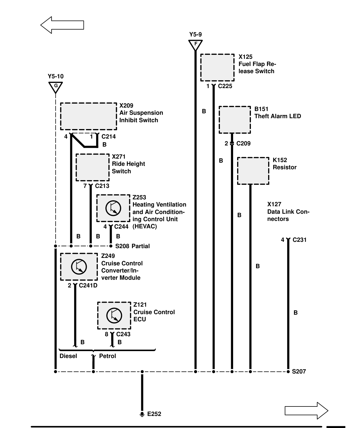
Components on this page
- B151 Theft Alarm LED
- K152 Resistor
- S208 Partial
- X125 Fuel Flap Release Switch
- X127 Data Link Connectors
- X209 Air Suspension Inhibit Switch
- X271 Ride Height Switch
- Z121 Cruise Control ECU
- Z249 Cruise Control Converter/Inverter Module C241D 2
Parts & tools for this job For 1995 Land Rover Range Rover
- TOOLDigital multimeterSearch: automotive digital multimeter
- PARTAssorted fuse kitSearch: car fuse assortment kit
- TOOLWire crimper and connector kitSearch: wire crimper connector kit
Links open Amazon search results in a new tab. As an Amazon Associate I earn from qualifying purchases.