
Manifolds and exhaust system (Exhaust manifold): Description and operation
- Make
- MG
- Model
- TF Factory Workshop Manual
- Year
- 2002–2005
- Section
- Description and operation › Exhaust manifold
EXHAUST MANIFOLD
The 4 branch fabricated steel exhaust manifold terminates in a flange with two outlet ports. The exhaust manifold flanges are sealed to the cylinder head and exhaust front pipe by gaskets.
EXHAUST SYSTEM
The exhaust system consists of a twin front pipe, terminating in an expansion chamber, a catalytic converter and a twin tail pipe which incorporates a large capacity silencer. The entire exhaust system is manufactured from stainless steel.
The silencer contains a series of expansion chambers, resonators and baffles designed to give an improved exhaust system, and reduce condensation to increase the life of the system.
NOTE: Service repair tail pipes are available to allow repair without replacing the silencer.
Two HO2S are installed in the exhaust system:
- One HO2S is installed upstream of the catalytic converter, in a mounting boss in the front pipe
- The 2nd HO2S is installed downstream of the catalytic converter, in a mounting boss in the catalytic converter outlet pipe
The catalytic converter operates in a closed loop system. The exhaust gases are monitored by the Engine Control Module (ECM) via signals sent from the upsteam HO2S in the exhaust front pipe. The ECM adjusts the fueling to maintain emissions acceptable to the catalytic converter. The ECM uses the signal from the downstream HO2S to monitor the condition of the catalytic converter. For information on the operation of the catalytic converter See ENGINE MANAGEMENT SYSTEM - MEMS, Information.
INLET MANIFOLD - MPi
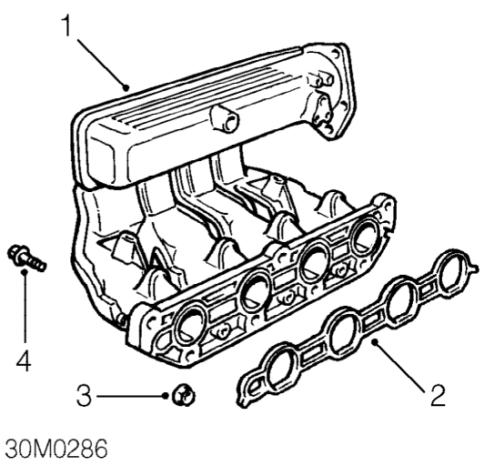
- Inlet manifold - plastic
- Gasket - inlet manifold
- Nut - inlet manifold - 3 off
- Bolt - inlet manifold - 4 off
The inlet manifold is a one piece plastic moulding attached to the cylinder head with a gasket interposed between the two components The throttle housing is bolted to the manifold chamber, sealing being effected by means of an ’O’ ring. The intake air temperature sensor is inserted above the pipe flange.
Parts & tools for this job For 2002 MG TF
- PARTExhaust gasketSearch: MG TF 2002 exhaust gasket
- TOOLPenetrating oilSearch: penetrating oil
- TOOLOBD2 scannerSearch: OBD2 scanner
Links open Amazon search results in a new tab. As an Amazon Associate I earn from qualifying purchases.