
Inlet manifold - VVC (Manifolds and exhaust system)
- Make
- MG
- Model
- TF Factory Workshop Manual
- Year
- 2002–2005
- Section
- Description and operation › Inlet manifold - VVC
Manifolds and exhaust systemInlet manifold - VVC
INLET MANIFOLD - VVC
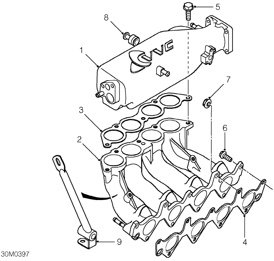
- Inlet manifold chamber
- Inlet manifold
- Gasket - manifold chamber to inlet manifold
- Gasket - inlet manifold to cylinder head
- Bolt - manifold chamber to inlet manifold
The alloy inlet manifold assembly comprises a manifold chamber bolted to the inlet manifold with a gasket interposed between the two components. The throttle housing is bolted to the manifold chamber and sealed with an ’O’ ring.
- Bolt - inlet manifold to cylinder head
- Nut - inlet manifold to cylinder head
- Vacuum pipe union
- Inlet manifold support stay
The manifold chamber incorporates the manifold absolute pressure sensor and brake servo vacuum hose union. The air intake temperature sensor is incorporated in the inlet manifold. The inlet manifold is attached to the cylinder head and sealed with a gasket. A strut between the inlet manifold and the cylinder block supports the inlet manifold assembly.
Parts & tools for this job For 2002 MG TF
- PARTExhaust gasketSearch: MG TF 2002 exhaust gasket
- TOOLPenetrating oilSearch: penetrating oil
- TOOLOBD2 scannerSearch: OBD2 scanner
Links open Amazon search results in a new tab. As an Amazon Associate I earn from qualifying purchases.