
Brake light switch (Brakes) (page 2 of 2)
- Make
- Rover
- Model
- 200 Workshop Manual
- Year
- 1995–1999
- Section
- Adjustments
BrakesBrake light switch · page 2 of 2
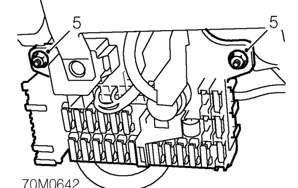
- Remove 2 nuts securing passenger compartment fuse box to mounting bracket.
- Release fuse box from mounting bracket.
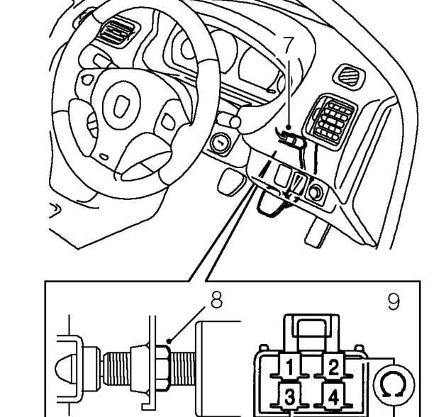
- Disconnect multiplug from brake light switch.
- Loosen locknut securing brake light switch to pedal box.
- Connect an ohmmeter across switch terminal 2 and 3.
- Screw switch in until an open circuit condition exists with the pedal released and a closed circuit condition exists with the pedal depressed.
- Tighten brake light switch locknut.
CAUTION: Ensure the switch does not prevent the brake pedal returning fully.
- Connect multiplug to brake light switch.
- Fit fuse box to mounting bracket, fit nuts and tighten to 10 Nm.
- Position closing panel to underside of fascia and secure with turnbuckles.
- Fit fuse box cover and secure with turnbuckles.
Parts & tools for this job For 1995 Rover 200
- TOOLOBD2 scannerSearch: OBD2 scanner
- TOOLDigital multimeterSearch: automotive digital multimeter
- TOOLBack-probe test leadsSearch: back probe test leads
Links open Amazon search results in a new tab. As an Amazon Associate I earn from qualifying purchases.