
Basic ignition timing
- Make
- Rover
- Model
- 200 Workshop Manual
- Year
- 1995–1999
- Section
- Description and operation › Basic ignition timing
BASIC IGNITION TIMING
Crankshaft position sensor
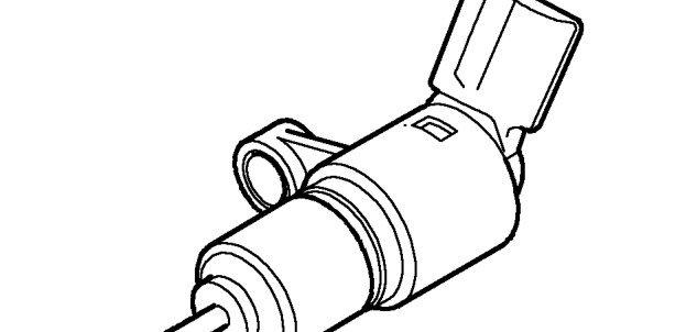
The speed and position of the engine is detected by the crankshaft position (CKP) sensor which is bolted to, and projects through, the engine adaptor plate adjacent to the flywheel.
The CKP sensor is an inductive sensor consisting of a bracket mounted body containing a coil and a permanent magnet which provides a magnetic field. The CKP sensor is situated so that an air gap exists between it and the flywheel. Air gap distance is critical for correct operation.
The flywheel incorporates a reluctor ring which consists of 32 poles spaced at 10° intervals, with 4 missing poles at 30°, 60°, 210° and 250°. The missing poles inform the ECM when to operate the groups of injectors. When the flywheel rotates, as a pole passes the CKP sensor it disturbs the magnetic field inducing a voltage pulse in the coil. This pulse is transmitted to the ECM.
By calculating the number of pulses that occur within a given time, the ECM can determine the engine speed. This is a primary input necessary to make the engine run.
Camshaft position sensor
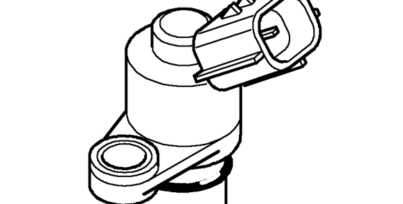
The camshaft position sensor has two functions. The first is to enable the ECM to run a sequential fuelling mode. The second is to measure the actual cam period, this measurment is achieved using teeth on the camshafts to indicate when the valve opens and closes.
If the camshaft position sensor fails when the engine is running, the engine will continue to run normally in sequential fuelling mode. If the sensor fails before the engine is started, the engine will start but run in grouped fuelling mode. The engine running in grouped fuelling mode can be usually detected by a reduced rev limit: 5000/5800 rpm in comparison to the normal rev limit of 7000/7300 rpm. Camshaft position sensor failure can be identified using TestBook.
Parts & tools for this job For 1995 Rover 200
- PARTEngine gasket setSearch: Rover 200 1995 engine gasket set
- TOOLTorque wrenchSearch: 3/8 inch torque wrench
- TOOLFeeler gauge setSearch: feeler gauge set
Links open Amazon search results in a new tab. As an Amazon Associate I earn from qualifying purchases.