
Abs5 anti-lock braking system (Brakes)
- Make
- Rover
- Model
- 400 Workshop Manual
- Year
- 1995–2000
- Section
- Description and operation › Abs5 anti-lock braking system
ABS5 ANTI-LOCK BRAKING SYSTEM
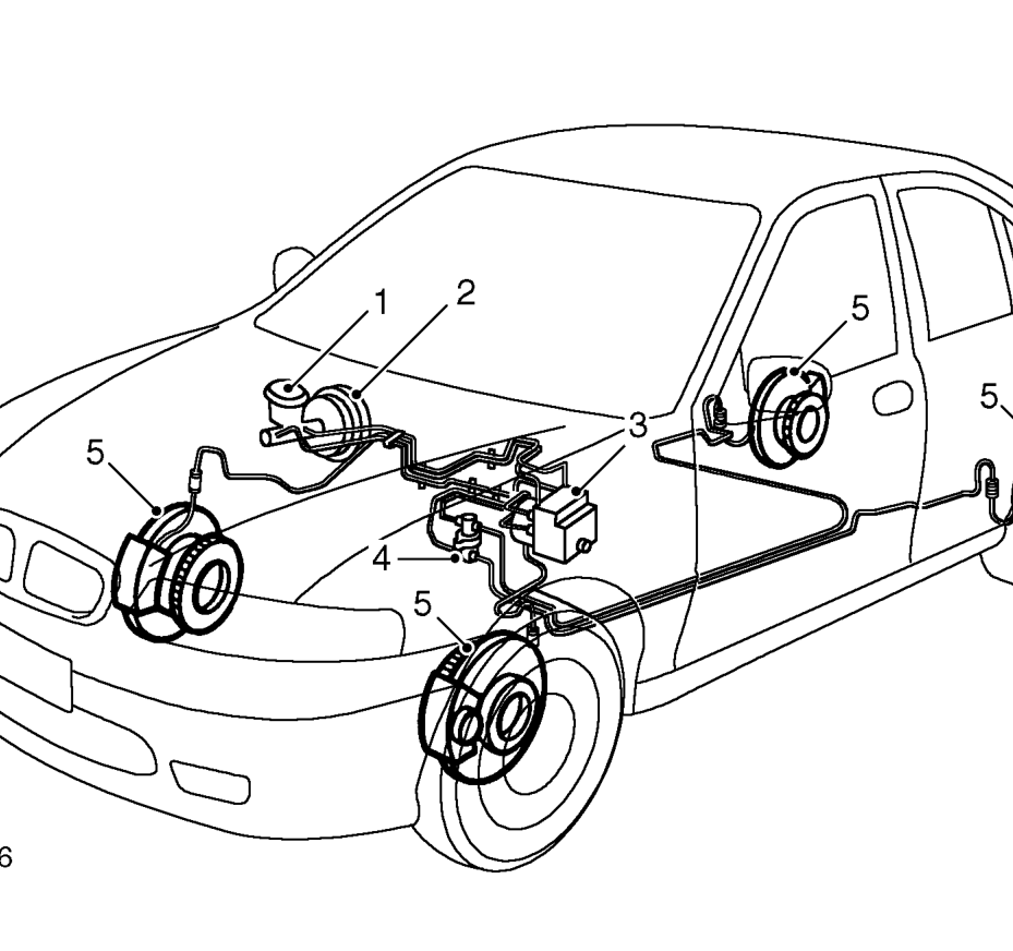
- Master cylinder
- Servo unit
- ABS5 modulator unit 416 Automatic models: Modulator unit positioned on RH valance
Description
The ABS5 system is an ECU controlled system deriving its input from four speed sensors mounted at the wheels which allow it to control the hydraulic modulator preventing the wheels locking during braking.
- Brake pressure proportioning valve
- Reluctor ring and wheel sensor
The operation of the ABS5 system is completely dependent upon electronic signals. To prevent the system responding to any inaccurate signals, a built in safety circuit monitors all electric and electronic signals, including battery voltage. If an inaccurate signal or low battery voltage is detected, the ABS system is shut down immediately and the warning light on the fascia is illuminated to inform the driver that the brake system will respond to pedal pressure in the same manner as a non ABS system.
Parts & tools for this job For 1995 Rover 400
- PARTBrake padsSearch: Rover 400 1995 brake pads
- TOOLBrake bleeder kitSearch: one man brake bleeder kit
- FLUIDBrake fluidSearch: brake fluid
Links open Amazon search results in a new tab. As an Amazon Associate I earn from qualifying purchases.