
Clutch system operation
- Make
- Rover
- Model
- 400 Workshop Manual
- Year
- 1995–2000
- Section
- Description and operation › Clutch system operation
CLUTCH SYSTEM OPERATION
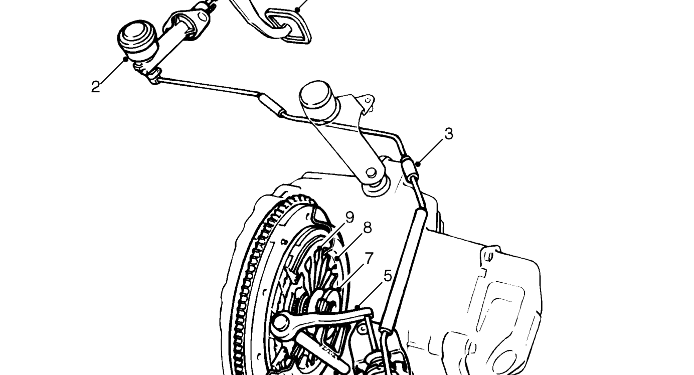
’K’ series illustrated
- Clutch pedal
- Clutch master cylinder
- Quick release connector
- Clutch slave cylinder
- Clutch release lever
The diaphragm type clutch is operated via a hydraulic system which is sealed for life and self bleeding.
When pressure is applied to the clutch pedal, fluid is pumped from the master cylinder to the slave cylinder causing the slave cylinder piston to apply pressure to the release lever. The release lever rotates the release fork and shaft. The release fork changes rotary movement of the release lever into linear movement pushing the release bearing against the pressure plate diaphragm fingers, applying pressure to the drive plate springs and dis-engaging the clutch.
- Release fork
- Release bearing
- Pressure plate
- Drive plate
When pressure is released from the clutch pedal the master cylinder piston is returned by a spring which causes a pressure decrease. The drop in pressure allows the diaphragm fingers to push the release bearing back, decreasing the pressure on the drive plate springs and re-engaging the clutch.
The clutch master cylinder is connected to the slave cylinder via a quick release connector. The quick release connector has a valve in each end preventing fluid loss when disconnected.
Parts & tools for this job For 1995 Rover 400
- PARTClutch kitSearch: Rover 400 1995 clutch kit
- TOOLClutch alignment toolSearch: clutch alignment tool
- FLUIDGear oilSearch: Rover 400 manual gearbox oil
Links open Amazon search results in a new tab. As an Amazon Associate I earn from qualifying purchases.