
Engine management system - EDC (Fuel system): Description and operation
- Make
- Rover
- Model
- 400 Workshop Manual
- Year
- 1995–2000
- Section
- Description and operation › Fuel system
Engine management system - EDCFuel system
FUEL SYSTEM
Fuel injection pump (electronic)
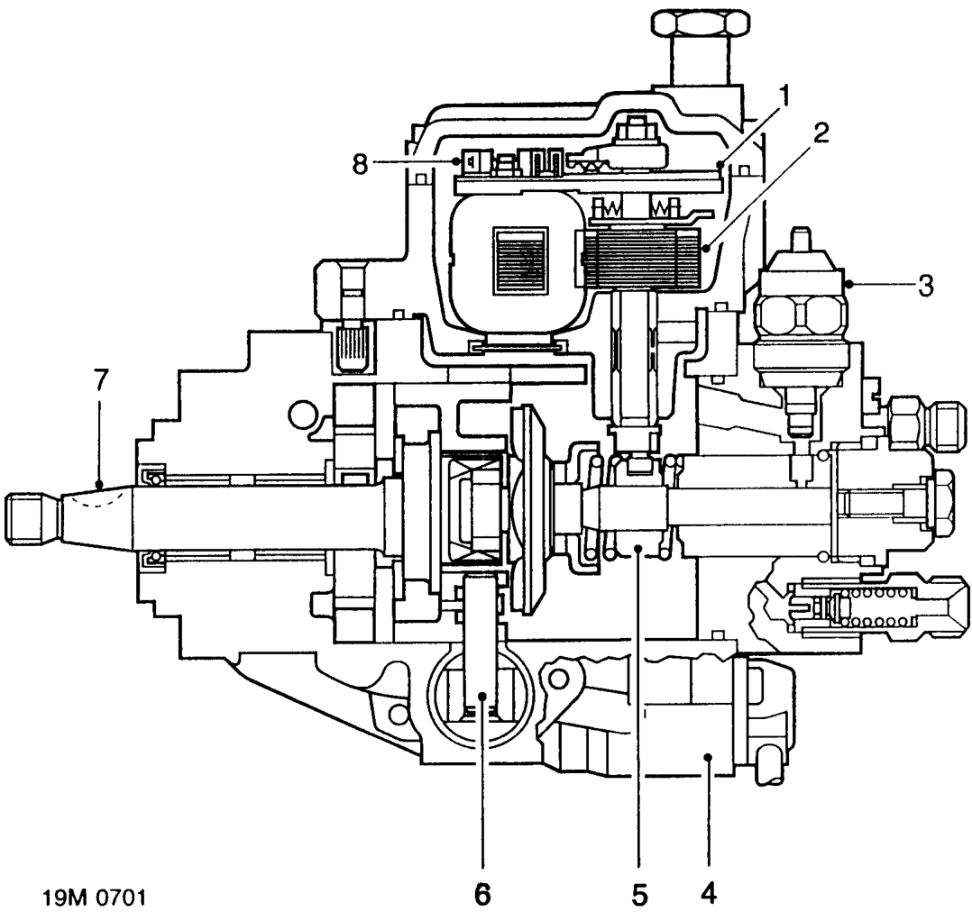
- Fuel quantity servo potentiometer
- Fuel quantity servo control unit
- Fuel shut off solenoid
- Injection timing device solenoid valve
The fuel injection pump is a vane-type pump, which is belt driven from the rear end of the camshaft. Fuel delivery from the pump to the injectors is regulated by the movement of a control spool. Movement of the control spool increases or decreases the fuel delivery rate to meet engine operating requirements.
The pump houses the following components which either provide feed back to the engine control module or are controlled by the engine control module:
- Control spool
- Injection timing device
- Injection pump drive shaft
- Fuel temperature sensor
Parts & tools for this job For 1995 Rover 400
- PARTFuel filterSearch: Rover 400 1995 fuel filter
- TOOLFuel pressure test kitSearch: fuel pressure test kit
- TOOLFuel line disconnect toolSearch: fuel line disconnect tool
Links open Amazon search results in a new tab. As an Amazon Associate I earn from qualifying purchases.