
Fuel temperature sensor (Engine management system - EDC)
- Make
- Rover
- Model
- 400 Workshop Manual
- Year
- 1995–2000
- Section
- Description and operation › Fuel temperature sensor
Fuel temperature sensor
Fuel temperature is monitored by a sensor located in the fuel injection pump. This sensor is of the negative temperature coefficient (NTC) type, designed to reduce its resistance with increasing temperature. The sensor is connected to earth and to a precision resistor inside the engine control module. A small current is fed through the precision resistor.
When the system is operating the engine control module regularly checks the sensor voltage. This is converted to a digital word that can be read by the microprocessor and converted to a temperature reading. As fuel density varies with temperature, the information received is used to calculate the correct quantity of fuel to inject.
Quantity servo control unit
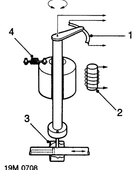
The servo control unit is used to accurately control the amount of fuel delivered to the injectors. The unit consists of a rotary magnet mounted on an eccentric shaft; the shaft engages with the control spool (3) of the pump. The rotary magnet is fitted with a return spring (4) and moves under the influence of a control coil (2). The magnet rotates through an arc of about 60 degrees moving the control spool from the closed position to the maximum fuel delivery position. The eccentric shaft engages with the control spool at one end, while the opposite end operates a rotary potentiometer (1).
When the control coil is energised the rotary magnet and eccentric shaft move against spring pressure. Rotary movement of the eccentric shaft is converted into linear movement of the control spool. This allows more fuel to be delivered to the injectors.
When the control coil is de-energised the return spring causes the rotary magnet and eccentric shaft to resume their original position. The control spool is moved to the closed position.
Parts & tools for this job For 1995 Rover 400
- TOOLOBD2 scannerSearch: OBD2 scanner
- TOOLDigital multimeterSearch: automotive digital multimeter
- TOOLBack-probe test leadsSearch: back probe test leads
Links open Amazon search results in a new tab. As an Amazon Associate I earn from qualifying purchases.