
Quantity servo potentiometer (Engine management system - EDC)
- Make
- Rover
- Model
- 400 Workshop Manual
- Year
- 1995–2000
- Section
- Description and operation › Quantity servo potentiometer
Quantity servo potentiometer
Mounted at the top of the servo control unit is a rotary potentiometer. As the eccentric shaft of the servo control unit moves, the wiper of the potentiometer is moved across the resistive part of the potentiometer. The voltage output from the potentiometer is proportional to the position of the control spool. From this input the engine control module can calculate the quantity of fuel being delivered by the pump and adjust the amount of fuel being delivered by energising the control coil to move the control spool.
Fuel cut-off solenoid

The fuel cut-off solenoid is located in the high pressure section of the injection pump. When the ignition is switched on the engine control module sends a signal to the solenoid. The solenoid energises opening a valve allowing fuel to flow.
When the ignition is switched off, or in the event of a serious engine problem, the control unit will remove the supply to the solenoid, closing the valve and cutting off the fuel supply to the injectors.
Injection timing device
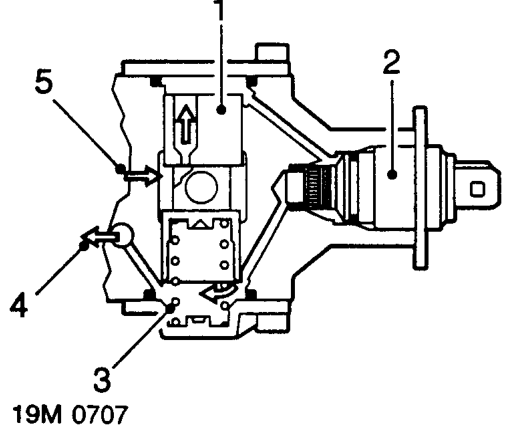
- Plunger
- Solenoid
- Spring
- Pump feed pressure
- pump internal pressure
The injection timing device consists of a spring loaded plunger and a solenoid. The spring loaded plunger acts against a cam plate driven by the injection pump shaft.The spring loaded plunger moves under the influence of pump working pressure.
The injection timing solenoid is responsible for the characteristic ’buzzing’ sound when the ignition is turned on. The solenoid operates at 50 Hz and by varying the operating frequency the engine control module alters the fuel pressure on the plunger, moving it against spring tension. By moving the plunger against the spring, the height of the plunger acting against the cam plate is changed, retarding the ignition. Injection timing is fully advanced with the solenoid de-energised.
The engine control module receives a feedback signal from the needle lift sensor and will attempt to correct the injection timing accordingly by altering the signal to the solenoid. If a change does not occur or differs by a substantial amount the engine control module will assume a fault exists and reduce the amount of fuel injected.
Parts & tools for this job For 1995 Rover 400
- PARTGlow plugsSearch: Rover 400 1995 glow plugs
- TOOLGlow plug socketSearch: glow plug socket
- TOOLDiesel compression testerSearch: diesel compression tester
Links open Amazon search results in a new tab. As an Amazon Associate I earn from qualifying purchases.