
Needle lift sensor (Engine management system - EDC)
- Make
- Rover
- Model
- 400 Workshop Manual
- Year
- 1995–2000
- Section
- Description and operation › Needle lift sensor
Needle lift sensor
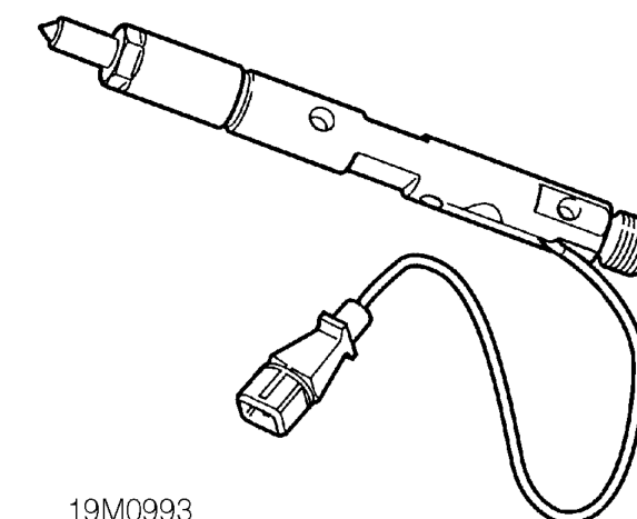
The needle lift sensor consists of a coil which surrounds the shaft of an extended injection needle. The coil is fed a DC supply from the control unit which produces a magnetic field.
When the needle is moved under the influence of fuel pressure, the magnetic field is disturbed which induces an ac voltage in the coil. The induced voltage is registered in the engine control module as a reference point for the start of the injection sequence.
The engine control module uses the input signals from the needle lift sensor, together with signal from the crankshaft sensor, to detect the actual start of injection. The engine control module, using inputs from the other sensors, calculates then adjusts the injection timing of the fuel pump to achieve optimum fuelling of the engine.
Fuel injection timing compensation components
Engine coolant temperature sensor
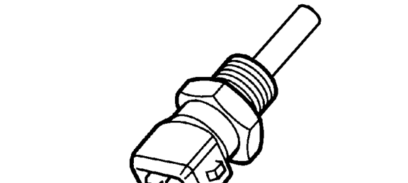
The engine coolant temperature sensor is a ’thermistor’ (a temperature dependent resistor), i.e. the voltage output varies in proportion to temperature. The sensor is located in the top of the coolant outlet elbow. The engine control module constantly monitors the signal and uses the information to correct the quantity of fuel injected and the injection timing especially during cold starting. During starting, output from the sensor determines how long the glow plugs are on.
Intake air temperature sensor - Bosch ECM only

The intake air temperature sensor is located in the side of the inlet manifold. This sensor is of the negative temperature coefficient (NTC) type, designed to reduce its resistance with increasing temperature. The engine control module receives a signal proportional to the temperature of the intake air. When used in conjunction with the signal from the manifold absolute pressure sensor and the crankshaft position sensor, the engine control module can calculate the volume of oxygen in the air and adjust the quantity of fuel being injected to achieve optimum fuelling of the engine.
Parts & tools for this job For 1995 Rover 400
- TOOLOBD2 scannerSearch: OBD2 scanner
- TOOLDigital multimeterSearch: automotive digital multimeter
- TOOLBack-probe test leadsSearch: back probe test leads
Links open Amazon search results in a new tab. As an Amazon Associate I earn from qualifying purchases.