
Brake pedal
- Make
- Rover
- Model
- 600 Rover 600 Repair Manual - Volumes 1 and 2 - 2nd Edition
- Section
- Brakes: information › Brake pedal
Brakes and ABSBrake pedal
BRAKE PEDAL
Pedal Height
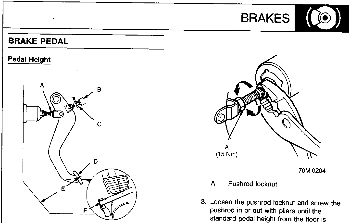
- A Pushrod locknut
- B Brake switch
- C Brake switch locknut
- D Brake pedal pad
- E Pedal height
- F Measuring point (cutout)
- Disconnect the brake switch connector, loosen the brake switch locknut and back off the brake switch until it is no longer touching the brake pedal.
- Measure the pedal height from the lower side centre of the pedal pad.
- Loosen the pushrod locknut and screw the pushrod in or out with pliers until the standard pedal height from the floor is reached. After adjustment, tighten the locknut firmly.
Note: Do not adjust the pedal height with the pushrod depressed.
Standard Pedal Height (floor mat removed):
M/T: 190mm minimum
A/T: 195mm minimum
Parts & tools for this job For Rover 600
- PARTBrake padsSearch: Rover 600 brake pads
- TOOLBrake bleeder kitSearch: one man brake bleeder kit
- FLUIDBrake fluidSearch: brake fluid
Links open Amazon search results in a new tab. As an Amazon Associate I earn from qualifying purchases.