
Workshop Manuals Factory service & repair Rover
01 Information02 General data03 Engine04 Engine management system – PGM-Fi05 Cooling system, manifold and exhaust06 Clutch07 Manual gearbox08 Automatic gearbox09 Drive shafts10 Differential – manual gearbox11 Differential – automatic gearbox12 Steering13 Suspension14 Brakes and ABS15 Brakes – ABS BY416 Body17 Heating and ventilation18 Electrical19 Supplementary restraint system (SRS)
Rover Rover 600 Repair Manual - Volumes 1 and 2 - 2nd Edition14 · Brakes and ABS
14 · Brakes

Pedal Free Play

Make
Rover
Model
600 Rover 600 Repair Manual - Volumes 1 and 2 - 2nd Edition
Section
Brakes: information › Pedal Free Play
Brakes and ABSPedal Free Play

Pedal Free Play
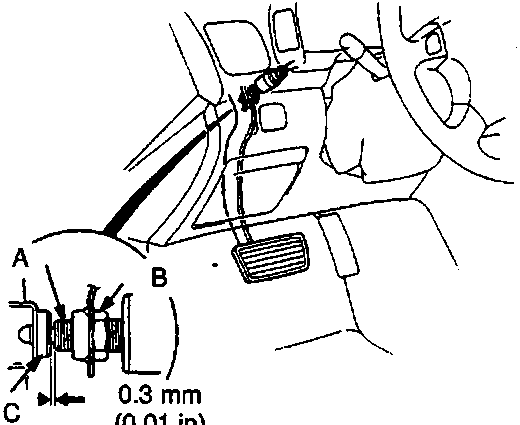
Diagram of brake switch installation showing threaded end, locknut, and pad with a 0.3 mm clearance dimension
A Threaded end B Locknut C Pad 4. Screw in the brake switch until its plunger is fully depressed (threaded end touching the pad on the pedal arm). Then back off the switch 1/4 turn to make 0.3mm (0.01 in) of clearance between the threaded end and pad. Tighten the locknut firmly. Connect the brake switch connector.

CAUTION: Make sure that the brake lights go off when the pedal is released.

5. Check the brake pedal free play.
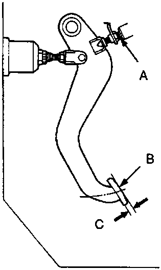
Diagram of brake pedal linkage showing brake switch, pedal pad, and pedal free play dimension
A Brake switch B Brake pedal pad C Pedal free play 1. Stop the engine and inspect the play on the pedal pad by pushing the pedal by hand.

Free Play: 1 – 5mm (1/16 – 13/64 in)

2. If the pedal free play is out of specification, adjust the brake switch.

CAUTION: If the pedal free play is insufficient, it may result in brake drag.

Parts & tools for this job For Rover 600

Links open Amazon search results in a new tab. As an Amazon Associate I earn from qualifying purchases.