
Inspection
- Make
- Rover
- Model
- 600 Rover 600 Repair Manual - Volumes 1 and 2 - 2nd Edition
- Section
- Cooling system: repairs › Inspection
Cooling system, manifold and exhaustInspection
Inspection
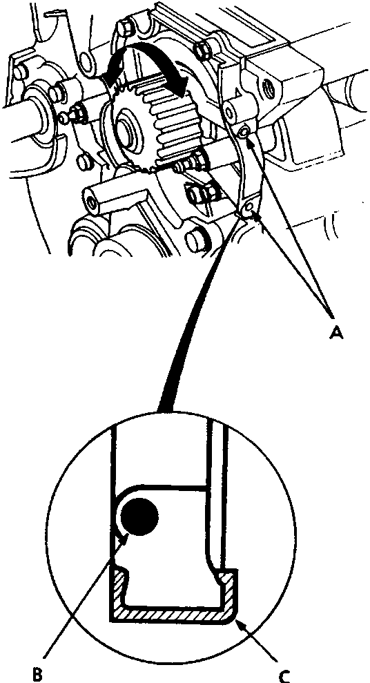
- A Bleed holes
- B Bleed hole
- C Rubber seal
- Remove the timing balancer belt and timing belt.
- Check that the water pump pulley turns freely.
- Check for signs of seal leakage.
Note: Small amount of "weeping" from bleed hole is normal.
Replacement
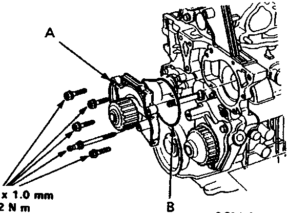
- A Water pump
- B O – ring
- Remove the timing balancer belt and timing belt.
- Unscrew the bolts, then remove the water pump.
- Install the water pump in the reverse order of removal. Replace the O – ring.
Parts & tools for this job For Rover 600
- FLUIDCoolantSearch: Rover coolant antifreeze
- PARTThermostatSearch: Rover 600 thermostat
- TOOLCooling system pressure testerSearch: cooling system pressure tester
Links open Amazon search results in a new tab. As an Amazon Associate I earn from qualifying purchases.