
Rear balancer (page 2 of 3)
- Make
- Rover
- Model
- 600 Rover 600 Repair Manual - Volumes 1 and 2 - 2nd Edition
- Section
- Engine lubrication: repairs
EngineRear balancer · page 2 of 3
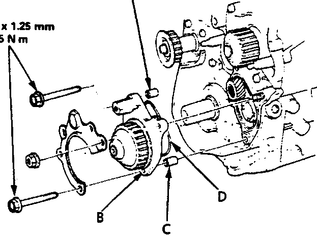
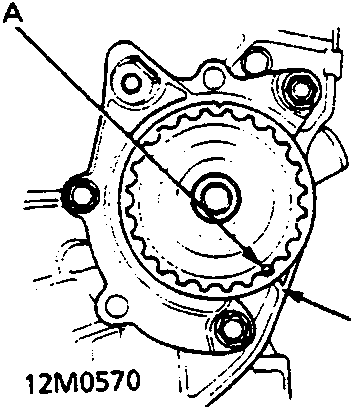
A Pointer on the Pulley
B Pointer on the Oil Pump
- Check alignment of pointers after installing the gear case.
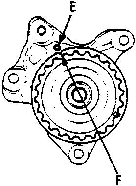
A Dowel Pin
B Balancer Gear Case
C Dowel Pin
D O - ring
E Pointer
F Groove
- Install the balancer gear case on the oil pump.
Note:
- Align the groove on the pulley edge to the pointer on the gear case while holding the rear balancer with the special tool, then install the gear case.
- Apply engine oil to the O - ring before installing it.
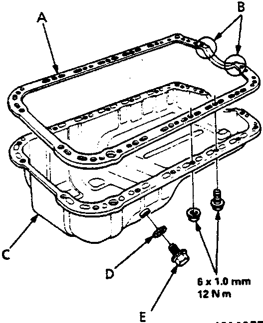
A Oil Sump Gasket
B Liquid Gasket
C Oil Sump
D Washer
E Drain Plug
- Install the oil sump.
Parts & tools for this job For Rover 600
- PARTEngine gasket setSearch: Rover 600 engine gasket set
- TOOLTorque wrenchSearch: 3/8 inch torque wrench
- TOOLFeeler gauge setSearch: feeler gauge set
Links open Amazon search results in a new tab. As an Amazon Associate I earn from qualifying purchases.