
Removal/Inspection/Installation (page 2 of 3)
- Make
- Rover
- Model
- 600 Rover 600 Repair Manual - Volumes 1 and 2 - 2nd Edition
- Section
- Engine lubrication: repairs
EngineRemoval/Inspection/Installation · page 2 of 3
If the housing – to – rotor axial clearance exceeds the service limit, replace the set of inner and outer rotors and/or the pump housing.
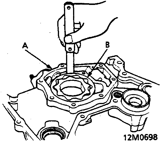
- A Pump Housing
- B Outer Rotor
- Check the housing – to – outer rotor radial clearance.
Housing – to – Outer Rotor Radial Clearance:
Standard (New): 0.10 ÷ 0.19 mm
Service Limit: 0.21 mm
If the housing – to – outer rotor radial clearance exceeds the service limit, replace the set of inner and outer rotors and/or the pump housing. - Inspect both rotors and the pump housing for scoring or other damage. Replace parts if necessary.
- Remove the old oil seals from the oil pump.
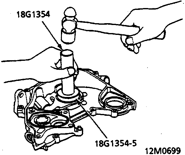
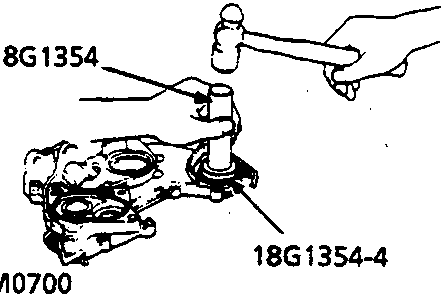
- Gently tap in the new oil seals until the special tool bottoms on the pump.
Note: The oil seals alone can be replaced without removing the oil pump using the special tool.
- Reassemble the oil pump, applying liquid thread lock to the pump housing screws.
- Check that the oil pump turns freely.
- Install a dowel pin and new O – rings on the pump.
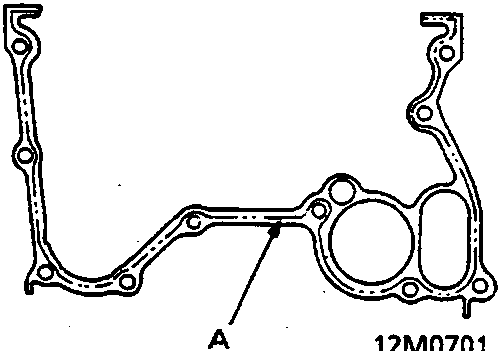
- A Broken Line
- Apply liquid gasket to the oil pump, along the broken lines shown, and install it.
Note:
- Use liquid gasket.
- Check that the mating surfaces are clean and dry before applying liquid gasket.
- Apply liquid gasket evenly, in a narrow bead centred on the mating surface.
- To prevent leakage of oil, apply liquid gasket to the inner threads of the bolt holes and the threads of the bolts.
Parts & tools for this job For Rover 600
- PARTEngine gasket setSearch: Rover 600 engine gasket set
- TOOLTorque wrenchSearch: 3/8 inch torque wrench
- TOOLFeeler gauge setSearch: feeler gauge set
Links open Amazon search results in a new tab. As an Amazon Associate I earn from qualifying purchases.