
Decrease pressure phase (Brakes)
- Make
- Rover
- Model
- 600 620 Diesel Repair Manual Supplement
- Year
- 1995–1999
- Section
- Description and operation › Decrease pressure phase
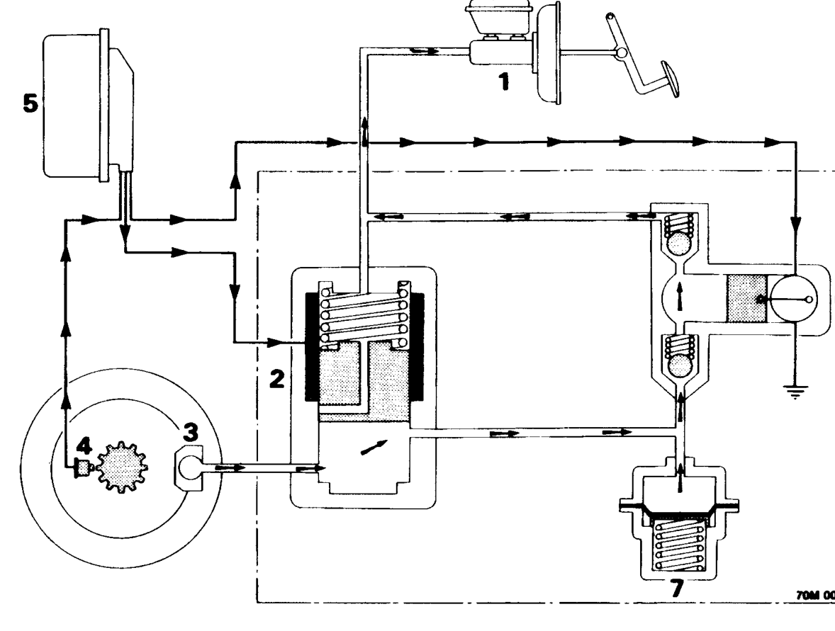
Decrease pressure phase
- Master cylinder
- Solenoid valve
- Wheel caliper
- Wheel sensors
If, however, the signal from the wheel sensor indicates that the wheel is still near locking point, with the pressure maintained, the ECU moves the solenoid valve to the next position allowing fluid from the caliper to pass to the return pump. At the same time the ECU sends a signal to start the return pump which pumps the fluid back to the master cylinder. Any excess fluid caused by the sudden drop in pressure, is temporarily stored in the accumulator.
When the signal to the ECU from the wheel speed sensor indicates that the wheel is not being braked sufficiently, the ECU removes its signal to the solenoid valve.
- Brake ECU
- Return pump
- Accumulator
The solenoid valve returns to its rest position allowing the pressure exerted on the brake pedal to be felt at the caliper.
This cycle continues until one of three conditions are met:
- The brake pedal is released.
- The vehicle has come to a rest.
- The speed of the wheels is almost the same as the reference speed.
The cycle is repeated at a rate of between 4 and 10 times a second, depending upon the condition of the road surface and can be detected by the driver as a pulsating movement of the brake pedal.
Parts & tools for this job For 1995 Rover 600
- PARTBrake padsSearch: Rover 600 1995 brake pads
- TOOLBrake bleeder kitSearch: one man brake bleeder kit
- FLUIDBrake fluidSearch: brake fluid
Links open Amazon search results in a new tab. As an Amazon Associate I earn from qualifying purchases.