
Maintain pressure phase (Brakes)
- Make
- Rover
- Model
- 600 620 Diesel Repair Manual Supplement
- Year
- 1995–1999
- Section
- Description and operation › Maintain pressure phase
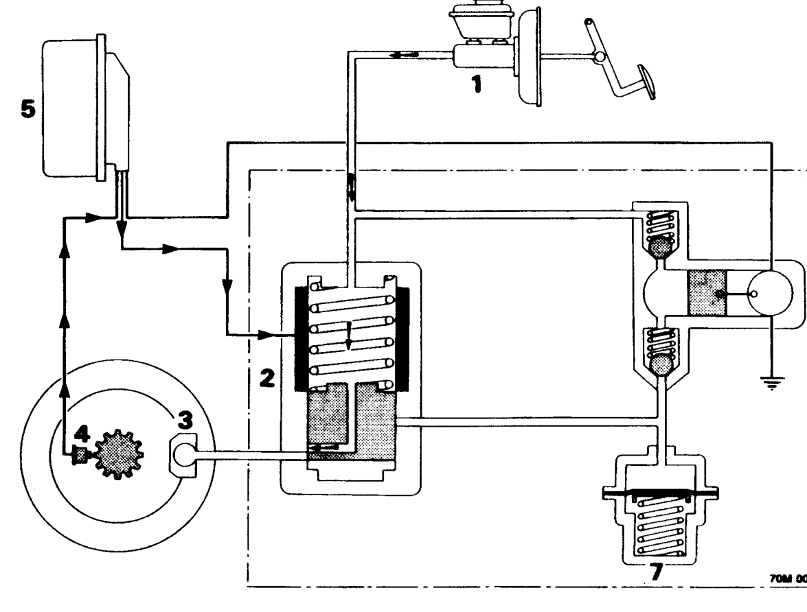
Maintain pressure phase
- Master cylinder
- Solenoid valve
- Wheel caliper
- Wheel sensors
When the brake pedal is applied brake fluid flows through the solenoid valves, at rest, to the caliper causing the vehicle to slow.
The ECU detects via the speed sensors if the vehicle speed is reducing too fast and will then send an electrical signal to the solenoid valve causing it to move closing the inlet port from the master cylinder preventing any pressure increase due to increased pedal pressure. This is the maintain pressure phase.
If the signal from the wheel sensor indicates to the ECU that, by maintaining the pressure, the wheel speed has increased and the wheel is now not being braked sufficiently, the ECU removes its signal to the solenoid valve returning the solenoid valve to its rest position allowing the pressure exerted on the brake pedal to be felt at the caliper.
- Brake ECU
- Return pump
- Accumulator
Parts & tools for this job For 1995 Rover 600
- PARTBrake padsSearch: Rover 600 1995 brake pads
- TOOLBrake bleeder kitSearch: one man brake bleeder kit
- FLUIDBrake fluidSearch: brake fluid
Links open Amazon search results in a new tab. As an Amazon Associate I earn from qualifying purchases.