
Abs2e hydraulic modulator ECU
- Make
- Rover
- Model
- 600 620 Diesel Repair Manual Supplement
- Year
- 1995–1999
- Section
- Repairs › Abs2e hydraulic modulator ECU
BrakesAbs2e hydraulic modulator ECU · page 1 of 2
Refit
- Position and align hydraulic modulator to mounting bracket.
- Tighten 3 mounting nuts to 10 Nm.
- Remove plugs from the ends of the brake pipes and from the modulator ports.
- Connect brake pipe unions to modulator unit. Ensure that the pipes are connected to their corresponding port on the modulator.
NOTE: The pipes are identified by labels on the pipes and the ports by stampings on the modulator. RF = RH Front, LF = LH Front RR = RH Rear, LR = LH Rear
- Tighten brake pipe unions to 22 Nm.
- Remove absorbent cloth from below modulator brake unions.
- Connect earth lead to modulator, fit and tighten nut.
- Fit ECU to hydraulic modulator. See this section.
- Connect battery earth lead.
- To ensure correct operation, the system MUST be tested using TestBook.
ABS2E HYDRAULIC MODULATOR ECU
Service repair no - 70.25.34
Remove
- Disconnect battery earth lead.
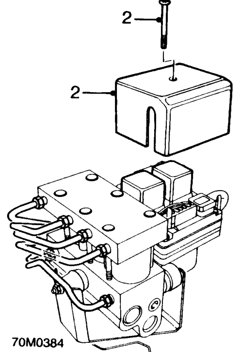
- Remove securing screw and relay cover from ECU.
Parts & tools for this job For 1995 Rover 600
- PARTBrake padsSearch: Rover 600 1995 brake pads
- TOOLBrake bleeder kitSearch: one man brake bleeder kit
- FLUIDBrake fluidSearch: brake fluid
Links open Amazon search results in a new tab. As an Amazon Associate I earn from qualifying purchases.