
Brake shoes and pads
- Make
- Rover
- Model
- Coupé, Cabriolet & Tourer 200/400 Coupé, Cabriolet & Tourer Workshop Manual
- Section
- General precautions and fitting instructions › Brake shoes and pads
Disconnect the battery earth lead before starting work, see ELECTRICAL PRECAUTIONS.
Always use the recommended service tool or a satisfactory equivalent where specified.
Protect exposed bearing and sealing surfaces and screw threads from damage.
Brake shoes and pads
WARNING: Always fit the correct grade and specification of brake linings and renew brake pads and brake shoes in axle sets only.
Brake hydraulics
WARNING: It is imperative that the correct brake fittings are used and that threads of components are compatible.
Always use two spanners when slackening or tightening brake pipe or hose connections. Ensure that hoses run in a natural curve and are not kinked or twisted. Fit brake pipes securely in their retaining clips and ensure that the pipe run cannot contact a potential chafing point.
Containers used for hydraulic fluid must be kept absolutely clean. Do not store hydraulic fluid in an unsealed container, it will absorb water and in this condition would be dangerous to use. Do not allow hydraulic fluid to be contaminated with mineral oil, or use a container which has previously contained mineral oil. Do not re – use fluid from the system. Always use clean brake fluid or a recommended alternative to clean hydraulic components. Fit a blanking cap to an hydraulic union and a plug to its socket after removal to prevent the ingress of dirt. Absolute cleanliness must be observed with hydraulic components.
Engine coolant caps and plugs
Extreme care is necessary when removing engine coolant caps and plugs when the engine is hot and especially if it is overheated. To avoid the possibility of scalding allow the engine to cool before attempting coolant cap or plug removal.
Cleaning components
Always use the recommended cleaning agent or equivalent.
Do not use degreasing equipment for components containing items which could be damaged by the use of this process. Whenever possible clean components and the area surrounding them before removal. Always observe scrupulous cleanliness when cleaning dismantled components.
Joints and joint faces
Fit joints dry unless otherwise specified in this Manual.
If gaskets and/or jointing compound is recommended for use; remove all traces of old jointing material prior to reassembly. Do not use a tool which will damage the joint faces and smooth out any scratches or burrs on the joint faces using an oil stone. Do not allow dirt or jointing material to enter any tapped holes.
Prior to reassembly, blow through any pipes, channels or crevices with compressed air.
Screw threads
Metric threads to ISO standards are used.
Damaged nuts, bolts and screws must always be discarded.
Cleaning up damaged threads with a die or tap impairs the strength and closeness of fit of the threads and is not recommended.
Castellated nuts must not be slacked back to accept a split – pin, except in those recommended cases when this forms part of an adjustment.
Do not allow oil or grease to enter blind threaded holes. The hydraulic action on screwing in the bolt or stud could split the housing.
Always tighten a nut or bolt to the recommended torque figure. Damaged or corroded threads can affect the torque reading.
To check or re – tighten a bolt or screw to a specified torque figure, first slacken a quarter of a turn, then retighten to the correct torque figure.
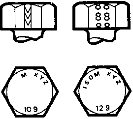
4NC 362
Bolt identification
An ISO metric bolt or screw made of steel and larger than 6 mm in diameter can be identified by either of the symbols ISO M or M embossed or indented on top of the head.
In addition to marks to identify the manufacturer, the head is also marked with symbols to indicate the strength grade, e.g. 8.8; 10.9; 12.9; 14.9. As an alternative, some bolts and screws have the M and strength grade symbol on the flats of the hexagon.
Parts & tools for this job For Rover Coupé, Cabriolet & Tourer
- PARTBrake padsSearch: Rover Coupé, Cabriolet & Tourer brake pads
- TOOLCaliper piston rewind toolSearch: brake caliper piston rewind tool
- FLUIDBrake fluidSearch: brake fluid
Links open Amazon search results in a new tab. As an Amazon Associate I earn from qualifying purchases.