
Heating and ventilation (Blower unit): Description and operation
- Make
- Rover
- Model
- Coupé, Cabriolet & Tourer 200/400 Coupé, Cabriolet & Tourer Workshop Manual
- Section
- Description and operation › Blower unit
Heating and ventilationBlower unit
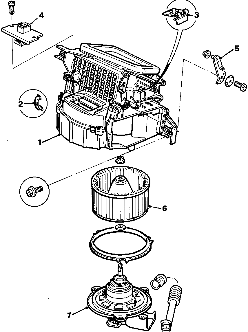
Heating and ventilation (Blower unit): Description and operation – diagram from the Heating and ventilation chapter of the Rover 200/400 Coupé, Cabriolet & Tourer Workshop Manual factory manual.
8RM 0928
BLOWER UNIT
- Air box
- Air box clip
- Cable clip
- Resistor unit
- Recirculation flap lever
- Fan
- Fan motor
Parts & tools for this job For Rover Coupé, Cabriolet & Tourer
- TOOLA/C manifold gauge setSearch: AC manifold gauge set
- TOOLUV leak detection kitSearch: AC UV leak detection kit
- PARTCabin filterSearch: Rover Coupé, Cabriolet & Tourer cabin filter
Links open Amazon search results in a new tab. As an Amazon Associate I earn from qualifying purchases.