
Heating and ventilation (Heater unit): Description and operation
- Make
- Rover
- Model
- Coupé, Cabriolet & Tourer 200/400 Coupé, Cabriolet & Tourer Workshop Manual
- Section
- Description and operation › Heater unit
Heating and ventilationHeater unit
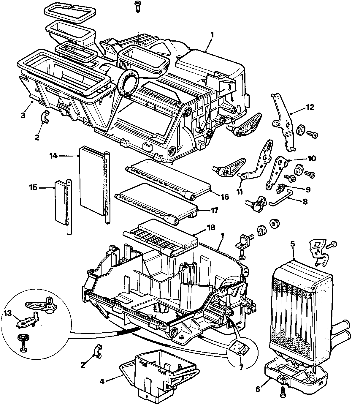
HEATER UNIT
1. Heater case
2. Heater case clip
3. Face level/windscreen duct
4. Foot level duct
5. Heater matrix
6. Heater matrix cover
7. Cable clip
8. Foot level flap link
9. Link clip
10. Foot level flap idler lever
11. Face level flap idler lever
12. Flap operating lever
13. Blend flap lever
14. Blend flap
15. Ambient air flap – centre face level vents
16. Distribution flap – windscreen
17. Distribution flap – face level vents
18. Distribution flap – foot level vents
Parts & tools for this job For Rover Coupé, Cabriolet & Tourer
- TOOLA/C manifold gauge setSearch: AC manifold gauge set
- TOOLUV leak detection kitSearch: AC UV leak detection kit
- PARTCabin filterSearch: Rover Coupé, Cabriolet & Tourer cabin filter
Links open Amazon search results in a new tab. As an Amazon Associate I earn from qualifying purchases.