
Air intake system
- Make
- Rover
- Model
- Coupé, Cabriolet & Tourer 200/400 Coupé, Cabriolet & Tourer Workshop Manual
- Section
- Description and operation › Air intake system
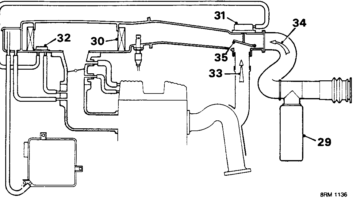
Air intake system
Intake air is drawn over a resonator (29) which reduces air intake noise, then passes via an intake air temperature control system and air filter (30) into the throttle body. Incorporated in the throttle body are the injector, pressure regulator, throttle disc, stepper motor and throttle potentiometer. Good cold driveability is achieved by a coolant heated inlet manifold and P.T.C. heater.
The intake air temperature control system relies on a vacuum servo (31), operated by a thermac valve (32), to divert intake air either over the exhaust manifold (33) or direct from the front of the vehicle (34).
When cold the thermac valve remains closed allowing depression to draw up the servo so positioning a flap (35) in the intake duct. This causes intake air to be drawn over the exhaust manifold, warming it before it passes to the air box.
As temperature increases the bi – metal strip in the thermac valve deforms, opening the valve and destroying the depression. The flap returns to its rest position as depression drops and causes cooler air to be drawn in direct from the front of the vehicle.
Inertia switch
The fuel pump circuit incorporates an inertia switch (19) which in the event of a sudden decceleration isolates the power supply to the fuel pump. The inertia switch is situated behind the vehicle centre console and can, if tripped, be reset by depressing the plunger.
WARNING: Check the integrity of the fuel system before the inertia switch is reset.
Diagnostic connector
A diagnostic connector (20) is provided to enable diagnosis to be carried out without disturbing the system electrical connections and to allow the E.C.U.’s ability to store certain faults to be utilised.

Parts & tools for this job For Rover Coupé, Cabriolet & Tourer
- PARTEngine gasket setSearch: Rover Coupé, Cabriolet & Tourer engine gasket set
- TOOLTorque wrenchSearch: 3/8 inch torque wrench
- TOOLFeeler gauge setSearch: feeler gauge set
Links open Amazon search results in a new tab. As an Amazon Associate I earn from qualifying purchases.