
Modular engine management system - SPi (Fuel system): Description and operation
- Make
- Rover
- Model
- Coupé, Cabriolet & Tourer 200/400 Coupé, Cabriolet & Tourer Workshop Manual
- Section
- Description and operation › Fuel system
Modular engine management system - SPiFuel system
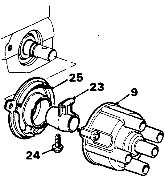
Distributor cap and rotor arm.
Fuel system
The M.E.M.S. Single Point injection system uses one injector (10) mounted in a throttle body, the solenoid operated injector directing its spray onto the back of the throttle disc. The amount of fuel delivered is determined by the length of time the injector is held open, this being governed by the E.C.U. in line with the inputs it receives. The fuel delivery system is of the pressure recirculation type, pressure being created by an electric pump (11) located inside the fuel tank and operated via the fuel pump relay (12), from which fuel is delivered via an under body line, to the fuel filter (13) where any impurities are removed. From the filter, fuel is pressurised around the injector housing against the pressure regulator (14), any excess pressure lifting the regulator and returning to the fuel tank. The air intake system includes a resonator to reduce intake noise and a stepper motor to control idle and fast idle speeds. An inlet manifold P.T.C. heater (15) controlled by the E.C.U. via a relay (16) and intake air temperature control system improve driveability during the warm – up period, and maintain intake air at the optimum temperature.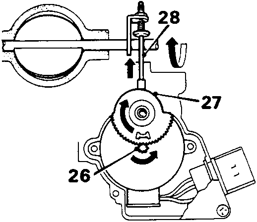
Calculation of air fuel ratio
The injector is a solenoid operated by the E.C.U. which earths the solenoid coil once for each cylinder cycle (twice per crankshaft revolution) during normal driving conditions. The amount of fuel injected is determined by how long the injector is held open (known as injector pulse width). To achieve the required air/fuel ratio the E.C.U. receives signals from the following inputs: Crankshaft sensor – engine speed. Manifold absolute pressure – engine load. Inlet air temperature sensor – inlet air temperature. Coolant temperature sensor – engine temperature. Throttle potentiometer – rate of throttle opening. Battery voltage – state of battery charge.Cruise air/fuel ratio.
The cruise air/fuel ratio is calculated by the speed/density method. Speed is determined by the crankshaft sensor and density (engine load) by the manifold absolute pressure and inlet air temperature (17) sensors. The E.C.U. contains the cruise air/fuel ratio in the form of a 2 dimensional map providing the required air/fuel ratio for 10 different engine speeds and 8 different inlet manifold density conditions. The selection of air/fuel ratio is further refined by the E.C.U. using the coolant temperature sensor, throttle potentiometer (18), throttle pedal switch and battery voltage.Parts & tools for this job For Rover Coupé, Cabriolet & Tourer
- PARTFuel filterSearch: Rover Coupé, Cabriolet & Tourer fuel filter
- TOOLFuel pressure test kitSearch: fuel pressure test kit
- TOOLFuel line disconnect toolSearch: fuel line disconnect tool
Links open Amazon search results in a new tab. As an Amazon Associate I earn from qualifying purchases.