
Sequence of operation:
- Make
- Rover
- Model
- Coupé, Cabriolet & Tourer 200/400 Coupé, Cabriolet & Tourer Workshop Manual
- Section
- Information › Sequence of operation:
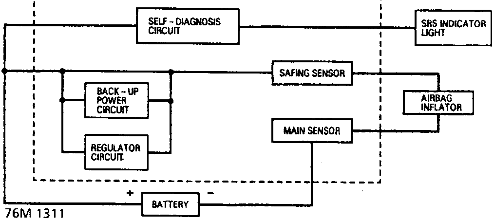
Note: The airbag control module is a non-serviceable component and no attempt to repair or modify the module should be made.
In the event of an accident involving a frontal impact, a sensor situated inside the airbag control unit monitors the force of the impact to determine whether the airbag should be inflated. A safing sensor wired in series with the main sensor allows the system to discriminate between driving on roads with potholes, striking kerbs, etc..., and an actual impact.
The sensors when activated supply voltage to the igniter circuit of the airbag. Grains of Nitrocellulose and Nitroglycerine inside the airbag module, ignite and combine in a chemical reaction to form a large amount of Nitrogen gas leading to inflation of the airbag in approximately 30 milli-seconds.
As the occupant moves forward into the airbag it immediately discharges the gas through a vent hole to provide progressive deceleration and reduce the risk of injuries.
A regulator circuit and a back up power circuit are connected in parallel with the car battery. The regulator circuit increases the stability of the SRS system by raising the voltage when the battery voltage drops. The back-up power circuit provides power in the event of the battery being disconnected due to the impact.
Sequence of operation:
- The main sensor and the safing sensor are activated.
- Power is supplied to the airbag igniter by the battery or the back-up circuit.
- The airbag deploys.
It takes about 0.1 seconds from the beginning of the airbag deployment until it is completely deflated.
Parts & tools for this job For Rover Coupé, Cabriolet & Tourer
- TOOLOBD2 scanner with SRSSearch: OBD2 scanner ABS SRS
- TOOLTrim removal tool kitSearch: trim removal tool kit
Links open Amazon search results in a new tab. As an Amazon Associate I earn from qualifying purchases.