seat Workshop Repair Guides

SEAT Workshop Service and Repair Manuals

Engine speed sender G28 : removing and installing > < Front sealing flange: Removing and installing
Sealing flange, flywheel side: Replace.
t  Removing the sealing flange with the sender wheel → Anchor
t  Fitting the sealing flange with the sender wheel → Anchor
t  A - Fit the seal along with the sender wheel on the fitting device -T10134- → Anchor
t  B - Fit the fitting device -T10134- with the sealing flange on the crankshaft flange → Anchor.
t  C - Screw the fitting device -T10134- onto the crankshaft flange → Anchor
t  D - Press the sender wheel with the fitting device -T10134- on the crankshaft flange → Anchor
t  E - Check the fitting position of the sender wheel on the crankshaft: → Anchor
t  F - Rectifying the position of the sender wheel → Anchor
t  Assembly: → Anchor
t  Tightening torques → Anchor
Remove the sealing flange with the sender wheel
   
Check the tool and equipment equivalence table according to the applicability between Seat / VW / Audi / Skoda → Chapter
Special tools and workshop equipment required
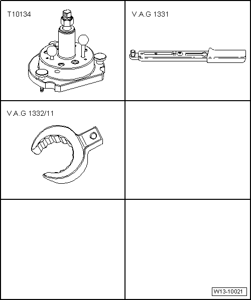
t  Centre guide -T10134-, see equivalent → Anchor
t  Tightening torque -VAG 1331-, see equivalent → Anchor
t  Wrench e/c 24 -VAG 1332/11-, see equivalent → Anchor
t  Depth gauge
t  Bolt M6 x 35 (3 units)
t  Bolt M7 x 35 (2 units)
l  Gearbox removed.
–  Remove flywheel → Chapter.
  W13-10021
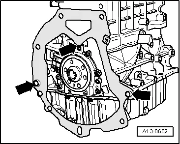
–  Unhook intermediate plate on sealing flange and on the dowel sleeves -arrows-.
–  Set the engine to TDC for cylinder 1 → Chapter.
–  Remove sump → Chapter.
  A13-0682
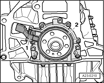
–  Remove the engine speed sender -G28-- 1- using the articulated Allen key.
  A23-0210
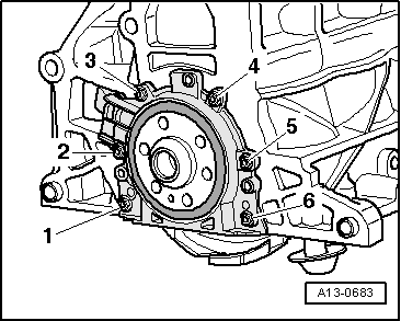
–  Unscrew the attachment bolts -1 … 6- from the sealing flange.
  Note
The sealing flange and the sender wheel are removed together from the crankshaft by the three M6 x 35 mm bolts.
  A13-0683
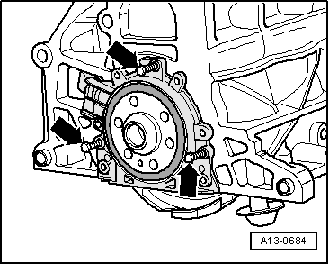
–  Screw three bolts M6 x 35 mm into the threaded spaces of the sealing flange-arrows-.
–  Screw in the 3 bolts M6x35 alternately max. 1/2 turns (180° per bolt) into the sealing flange.
–  Remove sealing flange together with sender wheel.
Fit the sealing flange with the sender wheel
  Note
t  The sealing flange with the PTFE seal is fitted with a pressure ring on the sealing lip. This pressure ring fulfils the function of an assembly sleeve and cannot be removed before fitting.
t  Once unwrapped, do not separate the sealing flange and the sender wheel or modify the position.
t  The sender wheel finds its position automatically when fitted to the position pin of the fitting device -T10134-.
t  The sealing flange and the seal make up one inseparable component and can only be replaced along with the sender wheel.
t  The assembly tool -T10134- is held in its installation position for the crankshaft by a guide pin which is inserted into a hole on the crankshaft.
  A13-0684
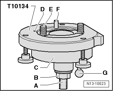
Structure of the fitting device -T10134-
A - Attachment surface
B - Conical hexagon bolt
C - Installation bell
D - Fastener
E - Allen key
F - Guide pin for diesel engines (black handle)
G - Guide pin for diesel engines (black handle)
  N13-10023
A - Fit the seal along with the sender wheel on the fitting device -T10134-
–  Tighten the hexagonal nut -B- to just before the threaded spindle attachment surface -A-.
  N13-10023
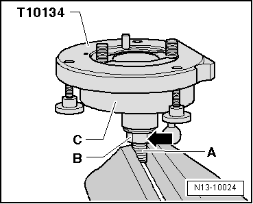
–  Secure the fitting device -T10134- on the attachment surface -B- of the threaded spindle in a vice.
–  Press down on the installation bell -C-, so that it rests -arrow- on the hexagonal bolt -B-.
  Note
Inner part of assembly device and assembly housing must be level with each other.
  N13-10024
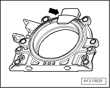
–  Unscrew the attachment clip -arrow- from the new sealing flange.
  Note
Do not remove the sender crown from the sealing flange or change its position.
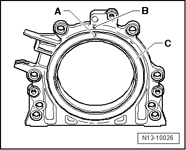
  N13-10025
l  The attachment hole -A- on the sender wheel -C- must coincide with the mark -B- on the sealing flange.
–  Secure the sealing flange by the front on a flat, clean surface.
  N13-10026
–  Press the sealing lip pressure ring -A- in the -direction of the arrow- downwards until it rests on the flat surface.
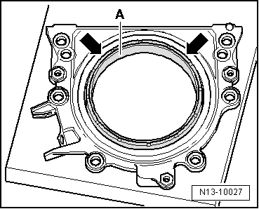
  N13-10027
l  The upper edge of the sender wheel and the front edge of the sealing flange must coincide -arrows-.
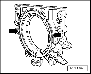
  N13-10028
–  Place the front of the sealing flange on the fitting device -T10134-, so that the fastener -B- sits into the hole -A- in the sender wheel.
  Note
Ensure that the sealing flange presses completely on the fitting device.
  N13-10029
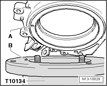
–  Tighten the sealing flange and the sealing lip pressure ring -B- while tightening the three knurled bolts -A- on the surface of the fitting device -T10134- so that the fastener cannot come out of the hole in the sender wheel.
  Note
Ensure that the sender wheel remains secured in the fitting device when fitting the sealing flange.
  N13-10030
B - Fit the fitting device -T10134-with the sealing flange on the crankshaft flange
l  The crankshaft flange must be free of oil and grease.
l  The engine is in TDC of cylinder 1.
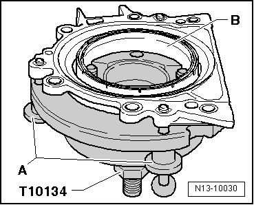
–  Screw in the hexagonal bolt -B- to the end of the threaded spindle.
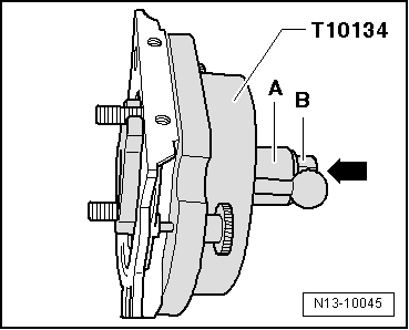
–  Press the threaded spindle on the fitting device -T10134- in the -direction of the arrow- until the hexagonal nut -B- sits on the installation bell -A-.
  N13-10045
–  Point the flat part of the installation bell towards the sealing surface of the engine block towards the oil sump.
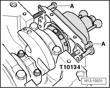
–  Secure the fitting device -T10134- to the crankshaft flange; to do so, tighten the Allen bolts -A- about 5 thread levels to the crankshaft flange.
  N13-10044
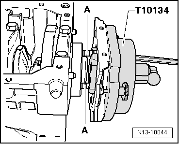
–  Screw in the 2 bolts M7×35 -A- on the engine block to guide the sealing flange.
  N13-10031
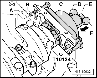
C - Screw the fitting device -T10134- onto the crankshaft flange
–  Move the installation bell -C- by hand in the -direction of the arrow- until the sealing lip pressure ring -B- sits on the crankshaft flange -A-.
–  Insert the guide pin for diesel engines (black handle) -D- into the crankshaft hole. In this way, the final fitting position of the sender wheel is established.
  Note
The guide pin for petrol engines (red handle) -F- cannot be inserted into the threaded hole.
–  Tighten the Allen bolts of the fitting device by hand.
–  Tighten the hexagonal bolt -E- on the threaded spindle until it comes into contact with the installation bell -C-.
  N13-10032
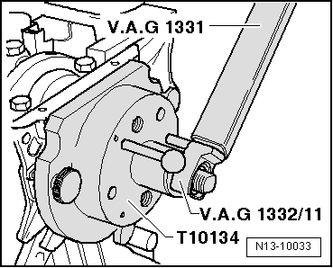
D - Press the sender wheel with the fitting device -T10134- on the crankshaft flange
–  Tighten the hexagon nut of the assembly tool -T10134- using the torque wrench -VAG 1331- and tighten using the insert 24 mm terminal -VAG 1332/11- to 35 Nm.
  Note
A small air gap must be present between cylinder block and sealing flange after tightening hexagon nut to 35 Nm.
  N13-10033
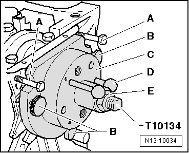
E - Check the fitting position of the sender wheel on the crankshaft.
–  Screw in the hexagonal bolt -E- to the end of the threaded spindle.
–  Unscrew the 2 bolts -A- of the engine block.
–  Unscrew the knurled bolts -B- from the sealing flange.
–  Remove the fitting device -T10134-.
–  Remove the pressure ring from the sealing lip.
  N13-10034
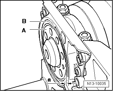
l  The sender wheel is positioned correctly on the crankshaft if the distance -a- between the crankshaft flange -A- and sender wheel -B- is 0.5 mm.
  N13-10035
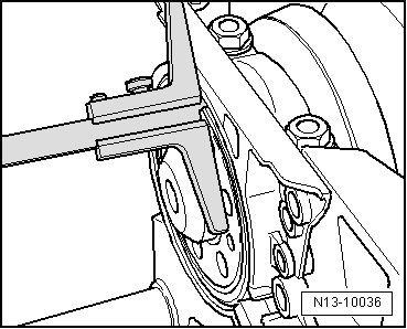
–  Fit the dial calliper onto the crankshaft flange.
–  Measure the distance -a- between crankshaft flange and sender wheel.
If distance -a- is too small:
–  Rectifying the position of the sender wheel → Anchor
If distance -A- is attained:
–  Carry out the remaining installation operations → Anchor.
F - Rectify the position of the sender wheel
  N13-10036
–  Secure the fitting device -T10134--A- to the crankshaft flange; to do so, tighten the Allen bolts by hand
–  Move the fitting device -T10134- by hand towards the sealing flange.
  N13-10044
–  Tighten the hexagonal bolt -E- on the threaded spindle until it comes into contact with the installation bell -C-.
  N13-10034
–  Tighten the hexagon nut of the assembly tool -T10134- using the torque wrench -VAG 1331- and tighten using the insert 24 mm terminal -VAG 1332/11- to 40 Nm.
–  Check the fitting position of the sender wheel on the crankshaft once more → Anchor.
If distance -a- is again too small:
–  Tighten the hexagonal bolt of the fitting device -T10134- to a torque of 45 Nm with the spanner -SAT 8010/24C-.
–  Check the fitting position of the sender wheel on the crankshaft once more → Anchor.
  N13-10033
Assembly
–  Screw in, alternating crossways, the attachment bolts -1 … 6 - on the sealing flange.
  A13-0683
–  Fit the engine speed sender -G28--1-.
–  Remove sump → Chapter.
  A23-0210
–  Fit intermediate plate on sealing flange, and press onto dowel sleeves -arrows-.
–  Fit the flywheel using new bolts. Tighten the attachment bolts to the torque 60 Nm + 90° (1/4 turn) → Chapter
Tightening torques
  A13-0682
ComponentNm
Sealing flange to cylinder block15 → Note
Engine speed sender -G28- to the engine block5
Flywheel bolts60 Nm + 90° (1/4 turn)

1)  Tighten alternatively diagonally
   

Engine speed sender G28 : removing and installing > < Front sealing flange: Removing and installing