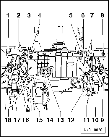
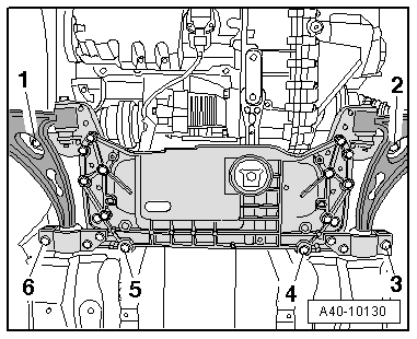
seat Workshop Repair Guides

SEAT Workshop Service and Repair Manuals

Ignition system, glow plug system > < Exhaust system: Rear silencer
Particle filter for four-wheel drive vehicles: Removing and installing
t  Removing → Anchor
t  Installing → Anchor
t  Tightening torques → Anchor
Check the tool and equipment equivalence table according to the applicability between Seat / VW / Audi / Skoda → Chapter
   
Special tools and workshop equipment required
t  Adjustment tool -T10096-, please see Correspondence → Anchor
t  Base -T20145-, see equivalent → Anchor
t  Counterhold -T20161-, see equivalent → Anchor
t  Tightening torque -VAG 1331-, see equivalent → Anchor
t  Tightening torque -V.A.G 1332-, see equivalent → Anchor
t  Hydraulic jack -VAG 1383A-, see equivalent → Anchor

   
t  Wrench kit -3337-, see equivalent → Anchor
  W00-0206
t  Wrench kit 17 mm -T10395-, see equivalent → Anchor
  W00-10767
t  Transport lock -T10404-, see equivalent → Anchor
Removing
  W00-10762
Continue the installation in the reverse order of removal sequence, observing the following:
–  Detach the outer -1- and inner -2- engine covers, by pulling them evenly upwards.
  E10-10038
–  Release the fuel and coolant hoses from their fittings on the air duct.
–  Remove bolt -1-.
–  Remove air duct by lifting retaining clips -arrows- slightly.
  A10-10266
–  Detach electrical connector -1- of the engine intake manifold flap -V157-.
–  Unscrew the bolts -arrows- and remove the intake manifold flap motor -V157-.
–  Disconnect the electrical connector -1- on the exhaust gas recirculation valve -N18- with the potentiometer for regulating exhaust gases -G212-.
–  Remove the electrical harness from the brackets and move to one side.
  A10-10029
–  Unscrew bolts -arrows-.
–  Remove the exhaust gas recirculation valve -N18- of the intake manifold.
  Note
For improved understanding, it is shown from the rear in the illustration with engine removed.
  A10-10030
–  Disconnect electrical connection -4- for lambda probe -G39-.
  A23-10003
–  Unscrew the pressure hose -4- of the particle filter.
–  Unscrew the lambda probe -3- with the lambda probe ring spanner -3337-.
–  Unbolt the support -2- of the pressure hoses.
–  Unscrew the exhaust gas temperature sender 2, bedplate 1 -G448--5- before the particle filter.
  A26-10173
–  Disconnect the electrical connector -arrow- for temperature sender 1 of the exhaust gases -G450-.
–  Unscrew exhaust gas pressure sensor 1 -G450- and remove together with the pressure hoses.
–  Unbolt the front right-hand wheel.
  A26-10188
–  Remove the centre noise insulation, fastening points -1 ... 3- → Bodywork, exterior fitting work; Rep. Gr.50.
  A10-1565
–  Remove the front right and left hand side wheel housing protections -fastening points 1 ... 3- → Bodywork, exterior fitting work; Rep. Gr.50.
  A10-1643
–  Remove the left hand side air hose; to do this, lift the retaining clips slightly -arrows-.
  A10-1834
–  Remove the front tunnel bridge -arrows-.
  Note
The flexible pipe connection (de-coupling element) in the front exhaust pipe must not be bent more than 10° - otherwise it can be damaged.
–  Unscrew the nuts on the double clamp -1-.
–  Remove the Cardan shaft → final drive 0AV and 0BR; Rep. Gr.39.
  A26-0734
–  Loosen the exhaust temperature sensor after particle filter -G527--1-, behind the particle filter.
–  Unscrew the pressure hoses -2- towards the pressure sensor 1 of the exhaust gases -G450-.
  A26-10189
–  Unscrew the insulating panel for the right half shaft from its mounting at the angular gears -arrows-.
  A34-10415
–  Unscrew the brackets -1- of the particle filter.
–  Remove the brackets.
  Note
Ignore positions -2, 3, 4 and 5-.
  A26-10173
–  Unscrew bolts -1 ... 3- and remove pendulum arm support.
  A10-1578
–  Unscrew the right and left link rod from the stabiliser bar -arrow-.
  A10-1141
–  Remove the support bolts of the particle filter and the engine block, and remove the support.
  A26-10190
–  Unbolt the exhaust system bracket -arrows-.
–  Partially remove the front part of the exhaust tube with particulate filter and position it over the steering box.
  Note
t  Fit the transport lock -T10404- onto the damping element of the front section of the exhaust pipe with particulate filter.
t  The damping element on the front section of the exhaust pipe with particulate filter should not be bent by more than 10º. Otherwise there is a risk of damage being caused.
–  Make sure the cables are not damaged when removing the forward section of the exhaust pipe with the particle filter.
  A26-0735
–  Unscrew the bolts -arrows- of the footwell zone trim.
  N48-10003
–  Undo bolt -1- and remove the cross member -2- from the steering box.
  N48-10004
–  Correctly position the hydraulic jack -VAG 1383A- with the base -T20145- and with the support tool -T20161- underneath the subframe.
  E40-10026
To be able to lock the subframe with the bearing, the locating pins -T10096- must be screwed to the positions -1-, -8-, -9- and -18- one after another.
  N40-10020
–  Replace the securing bolts of the attachment block on both sides one after the other, and instead of these, fix locating pins -T10096- and tighten them with a torque of 20 Nm.
  Note
The locating pins -T10096- can only be tightened to a torque of 20 Nm, any tighter will cause damage.
  N40-10022
–  Unscrew the remaining screws -1 … 6- for the mechanical support bridge.
  A40-10130
–  Carefully lower the engine assembly together with the steering box and the anti-roll bar with the help of the engine and gearbox jack -VAG 1383A-. When assembling, the following must be taken into account:
l  Ensure that the hydraulic lines of the steering box are not subjected to any stress.
l  Guide subframe past steering column.
l  The engine assembly must be lowered until the particulate filter can be removed.
  Note
Make sure that when lowering the mechanical support bridge it does not touch or scrape the engine compartment, since no element is dominant.
  Note
t  The damping element on the front section of the exhaust pipe with particulate filter should not be bent by more than 10º. Otherwise there is a risk of damage being caused.
t  Pay attention to the electrical connections and routing the cables without damaging.
  E40-10026
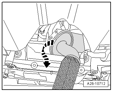
–  Remove the particle filter by turning it by 180° clockwise. In doing so, slightly press the engine / gear unit to the front and remove the filter between the tunnel and the mechanical bridge support unit.
Installing
Continue the installation in the reverse order of removal sequence, observing the following:
  Note
t  When replacing the particle filter, the transport protection on the coupling element should not be removed until just before fitting.
t  Fit the cable clamps in the same position as they were.
t  
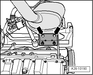
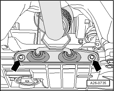
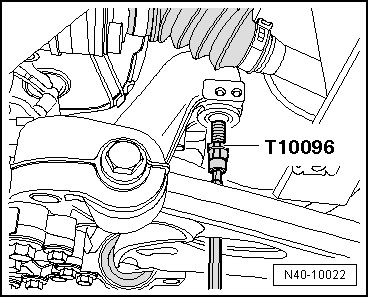
Ensure that the clamp for the particulate filter is fitted correctly → Anchor
t  Replace seals, gaskets and self-locking nuts.
t  The sleeves for the hoses and the supercharger air flow tubes should be free of oil and grease before fitting.
t  Secure all hose connections with the correct hose clips (original parts) → ETKA (Electronic parts catalogue).
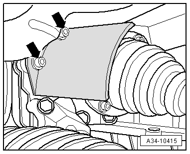
In order to correctly fit the clamp, pressure pipes and particle filter brackets, approach the elements without tightening:
t  Fit the gasket and the double clamp for the particle filter to the turbocharger.
t  
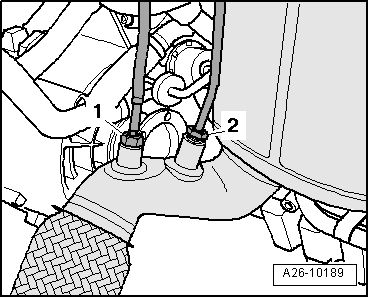
Manually screw in the injector pipe connections to the particle filter → Item.
t  Fit the injector pipe bracket to the particle filter → Item.
t  Screw the bracket bolts to the particle filter in by hand → Item.
Tightening torque sequence for the particle filter elements:
t  Clamp, 7 Nm.
t  Bracket on the particulate filter → Item
t  Pressure pipes → Item
t  Bracket of the pressure lines on the particulate filter → Item
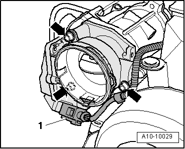
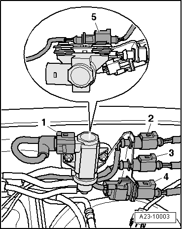
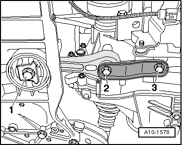
–  Remove the exhaust gas temperature sender 2, bedplate 1 -G448- → Item.
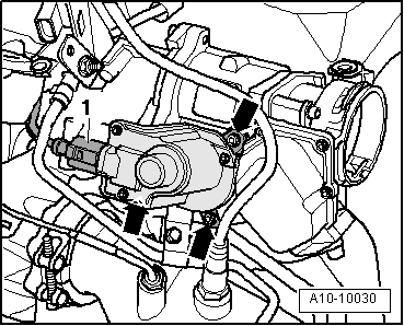
–  Install the temperature sender after the particulate filter -G527- → Item.
–  Install drive shaft → Rep. Gr.40.
–  Fit the bracket of the exhaust gas pressure sensor 1 -G450- on the cylinder head cap → Item.
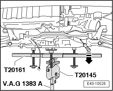
–  Align exhaust system without tension → Chapter
–  Following replacement of the particle filter, the “guided functions” → Vehicle diagnosis, testing and information system VAS 5051 must be adapted.
Tightening torques
  A26-10712
ComponentNm
Exhaust bracket to subframe23
Tube before turbocharger exhaust7
Particle filter support to particle filter23
Pendulum support to gearbox40 + 90° 1)2)
Heat shield to cylinder block35
Front crosspiece of the vehicle to the bodywork23
Pressure tube to particle filter40
l  1) Renew bolts.
l  2) 90° = one quarter turn


Ignition system, glow plug system > < Exhaust system: Rear silencer