| –
| Detach the outer -1- and inner -2- → Chapter by pulling them evenly upwards. |
| –
| Remove the supercharger air pipe completely between the charge air cooler and intake manifold flap motor -V157- → Chapter. |
| –
| Remove intake manifold flap motor -V157- → Chapter. |
| –
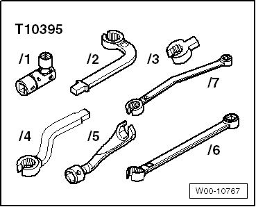
| Remove the exhaust gas temperature sender 1 -G235- with the T10395/5 tool from the 17 mm tool set -T10395-. |
| –
| Apply high-temperature paste -G 052 112 A3- on the thread of the exhaust gas temperature sender 1 -G235-. |
| –
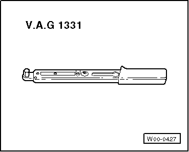
| Insert the sender by hand and tighten it using the T10395/5 tool. Tightening torque → Item. |
| –
| Install intake manifold flap motor -V157- → Chapter. |
| –
| Install the supercharger air pipe completely between the charge air cooler and intake manifold flap motor -V157- → Chapter. |
| Fit in reverse order from removal, remembering the following: |
| –
| Interrogate fault memory of engine control unit. No malfunction should be registered in the fault memory → Chapter |
|
|
|