seat Workshop Repair Guides

SEAT Workshop Service and Repair Manuals

F - Rectifying the position of the sender wheel > < D - Press the sender wheel with the centre guide T10017 onto the crankshaft flange:
E - Check the fitting position of the sender wheel on the crankshaft.
   
–  Unscrew the hexagonal bolt -A- to the end of the threaded spindle.
–  Remove screws M6 x 35 mm -B- from the cylinder block.
–  Unscrew the three knurled bolts -C- from the sealing flange.
–  Move the installation bell -D- of the assembly device back as far as the hexagonal nut -A- (only for sealing flange with elastic washer).
  N13-0421
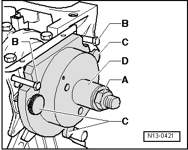
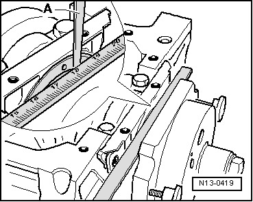
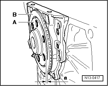
The sender wheel is in the correct position on the crankshaft when the distance -a- between the crankshaft flange -A-and the sender wheel -B- is 0.5 mm.
  Note
t  
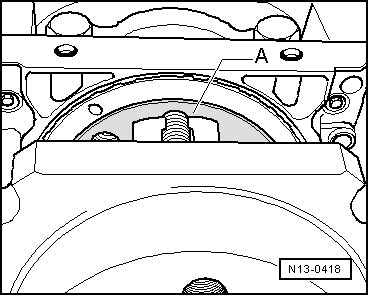
On the sealing flange with PTFE seal, completely unscrew the centre guide -T10017- and remove the sealing lip pressure ring.
t  To help identify distance -a-, the crankshaft flange is shown without the centre guide -T10017- bolted down.
  N13-0417
–  Fit a dial caliper against the crankshaft flange -A- (marker surface).
  N13-0418
–  Using a thickness gauge, measure -A- the distance -a- between the dial caliper and the sender wheel.
If distance -a- is too small:
–  Press the sender wheel again → Chapter.
If distance -a- is attained:
–  Remove the installation sleeve.
–  Bolt the new bolts securing the sealing flange in diagonal pairs. → Item
  N13-0419
–  Install engine speed sender -arrow-.
–  Fit the oil sump → Chapter.
–  Fit the intermediate plate.
–  Fit the flywheel → Chapter or the drive plate → Chapter.
  N13-0380

F - Rectifying the position of the sender wheel > < D - Press the sender wheel with the centre guide T10017 onto the crankshaft flange: