seat Workshop Repair Guides

SEAT Workshop Service and Repair Manuals

Checking vacuum unit for turbocharger > < Part II:
Removing and installing turbocharger
Special tools and workshop equipment required
   
t  Hose clip pliers -VAS 6340-
  W00-10380
t  
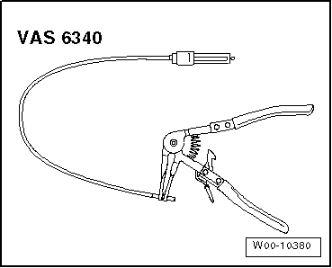
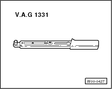
Torque wrench -V.A.G 1331-
Removal:
  Caution
If the turbocharger has suffered mechanical damage (e.g. damaged compressor wheel), it is not sufficient merely to fit a new turbocharger.
To prevent this from causing further damage, perform the following repairs:
t  
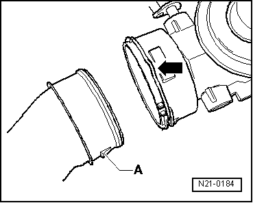
Check air filter housing, air filter element and intake hoses for soiling.
t  Check complete charged air routing and charge air cooler for foreign objects.
If foreign matter is found in the charge air system, clean all relevant ducts and hoses and renew the charge air cooler if necessary.
  Note
Before carrying out further work, disconnect battery earth strap. Check whether a coded radio is fitted. Obtain anti-theft coding if necessary.
–  Connect battery → Electrical system; Rep. gr.27
  W00-0427
–  Lift off engine cover panel at points -1- and pull it forwards in direction of -arrow-.
  N10-10281
–  Unbolt heat shield over turbocharger -arrows-.
–  Open and close expansion tank cap to release pressure in cooling system.
–  Drain coolant → Chapter.
All other vehicles continued
  Note
Pull coolant hoses off engine with hose clip pliers -VAS 6340-.
–  Observe rules for cleanliness → Chapter.
  N21-10220
–  Pull off connecting hoses -1- and coolant hoses -3-.
–  Unscrew bracket -2- and securing nuts -4- from turbocharger.
  N21-10065
–  Unscrew securing bolt -2- and remove upper coolant pipe.
  Note
The lower coolant pipe can only be removed following the removal of the catalytic converter.
–  Unscrew bolts -1- and remove pressure pipe.
–  Remove noise insulation → General body repairs, exterior; Rep. gr.50.
  N21-10081
–  Remove wiring for Lambda probe after catalytic converter -G130- and for alternator from cable guides -arrows-.
–  Pull connector off Lambda probe after catalytic converter -G130- and remove.
  N21-10066
–  Open hose clip -3- and remove charge air pipe -2-.
–  Unbolt exhaust pipe from catalytic converter -arrows-.
  N21-10067
–  Unbolt exhaust pipe to rear silencer -arrows-.
  N21-10068
–  Loosen securing bolts of clamp -arrows- and pull exhaust pipe to rear.
–  Also pull out exhaust pipe together with flexible joint.
–  Remove catalytic converter downwards.
–  Removing poly V-belt → Chapter
  N21-10069
–  Unscrew securing bolts for tensioning element -arrows- and remove it.
–  Remove upper alternator bolt and swing alternator out forwards.
–  Unscrew securing bolt -arrow- for oil return pipe -2- from turbocharger.
  N21-10071
–  Pull oil return pipe downwards.
–  Unbolt charge air hose -1- from turbocharger.
–  Unscrew banjo bolts of oil supply pipe -arrows- at turbocharger and at valve timing housing.
  N21-10105
–  Remove oil supply pipe.
–  Unscrew all securing nuts from exhaust manifold -1-.
–  Pull exhaust manifold out upwards with turbocharger.
  Note
The turbocharger can only be renewed together with the exhaust manifold.
Installation
  Caution
Oil supply line must be renewed when installing a new turbocharger.
Installation is carried out in the reverse sequence; note the following:
t  Renew studs and fastening nuts.
t  Screw studs into cylinder head until they project only by 25 mm.
t  Observe correct tightening sequence: Positions -A- to -I- → Chapter.
t  Renew seals, gaskets and self-locking nuts.
t  Fill turbocharger with engine oil at oil supply line connection.
t  After installing turbocharger, run engine for about 1 minute at idling speed to ensure that oil is supplied to turbocharger.
t  Hose connections and hoses for charge air system must be free from oil and grease before fitting.
t  Secure all hose connections with hose clips which conform to production standard.
t  Install exhaust system and align it free of stress.
  N21-10225
t  When installing air pipes with plug-in connector, ensure that securing clip -arrow- audibly engages into retaining lug -A-.
–  Fitting hose connections with plug-in connectors → Chapter
Tightening torques: → Chapter
  Caution
The screw-type clips on the charge air pipes must be tightened to 5.5 Nm. If the torque is too low or too high, the charge air hose may slip off the charge air pipe during vehicle operation.
–  Exhaust turbocharger - assembly overview → Chapter.
–  Assembly overview - charge air system → Chapter.
–  Catalytic converter and attaching parts - Assembly overview → Chapter
  N21-0184
–  Push down engine cover panel at points -1- in direction of -arrow- until engine cover panel engages.
  N10-10281

Checking vacuum unit for turbocharger > < Part II: